LG LWHD1800HR Service Manual - Page 16
Electrical parts
 |
View all LG LWHD1800HR manuals
Add to My Manuals
Save this manual to your list of manuals |
Page 16 highlights
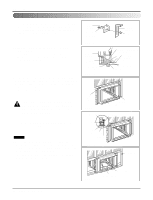
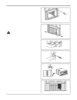
Disassembly 6. Fan 1. Remove the cabinet. (Refer to section 2) 2. Remove the brace and shroud cover. (Refer to section 4) 3. Remove the side cover with 2 screws.(See Fig. 23) 4. Remove the 5 or 6 screws which fasten the condenser. 5. Move the condenser sideways carefully. 6. Remove the clamp which secures the fan. 7. Remove the fan. (See Fig. 23) 8. Re-install the components by referring to the removal procedure, above. 7. Shroud 1. Remove the fan. (Refer to section 6) 2. Remove the 2 screws which fasten the shroud. 3. Remove the shroud. (See Fig. 24) 4. Re-install the component by referring to the removal procedure, above. Electrical parts 8. Motor 1. Remove the cabinet. (Refer to section 2) 2. Remove the cover control and disconnect a wire hous- ing in control box. (Refer to section 3) 3. Remove the blower. (Refer to section 5) 4. Remove the fan. (Refer to section 6) 5. Remove the 4 screws which fasten the motor. (See Fig. 25) 6. Remove the motor. 7. Re-install the components by referring to the removal procedure, above. 9. Compressor 1. Remove the cabinet. (Refer to section 2) 2. Discharge the refrigerant system using FreonTM Recovery System. If there is no valve to attach the recovery system, install one (such as a watco a-1) before venting the FreonTM . Leave the valve in place after servicing the system. 3. Disconnect the 3 leads from the compressor. 4. After purging the unit completely, unbraze the suction and discharge tubes at the compressor connections. 5. Remove the 3 nuts and the 3 washers which fasten the compressor. (See Fig. 26) 6. Remove the compressor. 7. Re-instill the components by referring to the removal procedure, above. Figure 23 Figure 24 Figure 25 Figure 26 Service Manual 16
-
 1
1 -
2
-
3
-
4
-
5
-
6
-
7
-
8
-
9
-
10
-
 11
11 -
 12
12 -
 13
13 -
 14
14 -
 15
15 -
 16
16 -
 17
17 -
 18
18 -
 19
19 -
 20
20 -
 21
21 -
22
-
23
-
24
-
25
-
26
-
27
-
28
-
29
-
30
-
31
 |
 |
