LG MHEC1737F INSTALLATION - Page 13
Step 5: Install the Mounting Plate
 |
View all LG MHEC1737F manuals
Add to My Manuals
Save this manual to your list of manuals |
Page 13 highlights
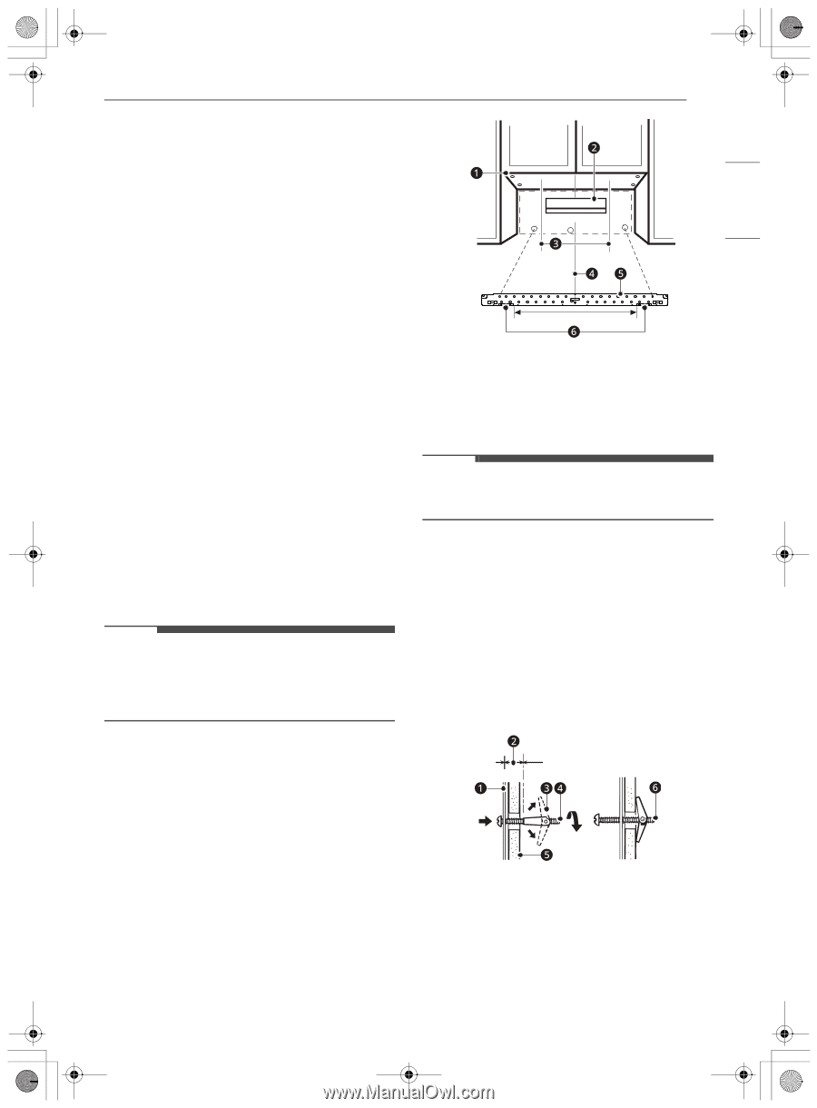
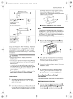
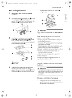
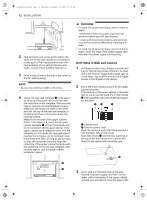
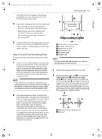
us_main.book.book Page 13 Thursday, November 25, 2021 10:15 AM ENGLISH hole with the power supply cord bushing (supplied) to prevent damage to the cord from the rough metal edge. 4 Cut out the venting areas (with the saber saw) • Roof-venting: cut out the shaded area marked L on the upper cabinet template. • Wall-venting: cut out the shaded area marked F on the rear wall template. • Room-venting: go to Step 5: Install the Mounting Plate. 5 Complete whichever venting system you have chosen. Use caulking compound to seal the exterior wall or roof opening around the wall cap or roof cap. Step 5: Install the Mounting Plate The oven must be connected to at least one wall stud. 1 Center the rear wall template in the space by lining up the plumb line on the wall with the centerline on the template. Then securely tape or tack the rear wall template in place. Make sure the minimum width is 30 inches and that the top of the rear wall template is located a minimum of 30 inches above the cooking surface. NOTE • If the cabinets are not plumb, adjust the rear wall template to the cabinets. If the front edge of the cabinet is lower than the back edge, adjust the template to be level with the cabinet front. 2 Drill holes at points A and B. Drill the third hole inside area C, through one of the bottom holes to match the location of a stud. If there is a stud, drill a 3/16 hole for lag screws. If there is no stud, drill a 5/8 hole for toggle bolts. These holes must be used for mounting. If the holes are not used, the installation will not be secure. The installer must use these holes for proper installation. Use toggle bolts through these holes, unless one of them lines up with a stud. Use a lag screw for studs. Make sure to use at least 1 lag screw in a stud, and 2 toggle bolts in the drywall or the plaster. INSTALLATION 13 A B A B C a Minimum 66" from the floor b For wall - venting only c Draw lines on studs d Draw center Line e Mounting plate f Support tab NOTE • Cut out the shaded area marked F on the rear wall template for wall-venting. 3 Remove the template from the rear wall. 4 Attach the plate to the wall e. To use spring toggle head bolts d: Remove the toggle wings c from the bolts. Insert the bolts into the mounting plate a and replace the spring toggle head to 3/4 of the length past the bolt ends. Insert the spring toggle head into the holes in the wall to mount the plate. You may pull forward on the plate to help in tightening the toggle bolts. Tighten all bolts. b Space more than wall thickness f Bolt end
-
 1
1 -
2
-
3
-
4
-
5
-
6
-
7
-
 8
8 -
 9
9 -
 10
10 -
 11
11 -
 12
12 -
 13
13 -
 14
14 -
 15
15 -
 16
16
 |
 |