Lantronix SISPM1040-3166-L Installation Guide Rev G - Page 28
Installing SFP Modules, Connecting Powered Devices (PDs), Connecting Power, Power Connection, Warning
 |
View all Lantronix SISPM1040-3166-L manuals
Add to My Manuals
Save this manual to your list of manuals |
Page 28 highlights
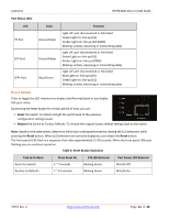
Lantronix SISPM1040-3xxx-L Install Guide Installing SFP Modules You can install or remove a mini-GBIC SFP module from an SFP port without having to power off the switch. Note: The SFP ports should use UL Listed Optional Transceiver product, Rated 3.3Vdc, Laser Class 1. See the SFP manual for specific cautions, warnings, and instructions. See the SFP page for our full range of Optical Devices. 1. Insert the module into the SFP port. 2. Press firmly to ensure that the module seats into the connector. Connecting Powered Devices (PDs) Note that this device does not comply with IEEE 802.3at at 48‐51.4 VDC, or with IEE 802.3bt at 48‐53.4 VDC. The old device label states 48‐57 VDC. The latest device label indicates: • 802.3af: 48‐57VDC • 802.3at: 52‐57VDC • 802.3bt: 54‐57VDC This device drops ~1.3V from Vin to PSEout. IEEE requires these PSEout voltages at the PSE output into the cable: • 802.3af: 44VDC • 802.3at: 50VDC • 802.3bt: 52VDC Not meeting this PSEout requirement may cause power up failures or power cycling with devices drawing maximum power with maximum cable loss. Connecting Power The SISPM1040‐3248‐L/SISPM1040-3166-L has one AC power input and Dual DC power inputs. It doesn't support a secondary AC Power Supply option. It provides redundancy between AC and dual DC power inputs and the AC power input has high priority. The switch can use DC and AC at the same time. For redundancy, AC takes priority over DC; see the Install Guide. Power Connection: Warning: Connect the power supply to the switch first, and then connect the power supply to power. Otherwise catastrophic product failure may occur. 1. Verify that power is off to the DC circuit that you are going to attach to the switch PoE DC-input connector. This can be either of the two power supplies (AC-input or DCinput) or site source DC. 2. As an added precaution, place an appropriate safety flag and lockout device at the source power circuit breaker, or place a piece of adhesive tape over the circuit breaker handle to prevent accidental power restoration while you are working on the circuit. Power Disconnection: To disconnect power from the switch after a successfully boot: 1. Turn off power to the switch. 2. Disconnect the cables. 33762 Rev. G https://www.lantronix.com/ Page 28 of 48
-
 1
1 -
2
-
3
-
4
-
5
-
6
-
7
-
8
-
9
-
10
-
11
-
12
-
13
-
14
-
15
-
16
-
17
-
18
-
19
-
20
-
21
-
22
-
 23
23 -
 24
24 -
 25
25 -
 26
26 -
 27
27 -
 28
28 -
 29
29 -
 30
30 -
 31
31 -
 32
32 -
 33
33 -
34
-
35
-
36
-
37
-
38
-
39
-
40
-
41
-
42
-
43
-
44
-
45
-
46
-
47
-
48
 |
 |
