Lantronix SISTP1040-551-LRT SISTP1040-551-LRT Install Guide Rev B - Page 16
Power Connection, IEEE 802.3bt Power Input Ripple and Noise Specification
 |
View all Lantronix SISTP1040-551-LRT manuals
Add to My Manuals
Save this manual to your list of manuals |
Page 16 highlights
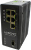
Lantronix SISTP1040-551-LRT Install Guide Power Connection The switch can be powered from one or two power supplies. Switch power input ranges are: • 48V-57V for PoE • 50V-57V for PoE+ • 52V-57V for PoE++ 1. Insert the terminal block into the switch top panel receptacle. 2. Insert the positive and negative wires (AWG 14-26) into the PWR + and PWR - contacts on the terminal block and tighten the wire-clamp screws to prevent the wires from being loosened. 3. Caution: DC power must be connected to an isolated power supply. See chapter 3 Power Supply Information" on page 17 below. 4. Verify proper LED status; see chapter 4 Troubleshooting LED Status Indicators on page 20 below. IEEE 802.3bt Power Input Ripple and Noise Specification f< 500 Hz 500 Hz to 150 kHz 150 kHz to 500 kHz 500 kHz to 1 MHz VNoise Vpp 0.5 0.2 0.15 0.1 33841 Rev. B https://www.lantronix.com/ Page 16 of 26
-
 1
1 -
2
-
3
-
4
-
5
-
6
-
7
-
8
-
9
-
10
-
 11
11 -
 12
12 -
 13
13 -
 14
14 -
 15
15 -
 16
16 -
 17
17 -
 18
18 -
 19
19 -
 20
20 -
 21
21 -
22
-
23
-
24
-
25
-
26
 |
 |
