Lantronix XPort XPort - Integration Guide
Lantronix XPort Manual
 |
View all Lantronix XPort manuals
Add to My Manuals
Save this manual to your list of manuals |
Lantronix XPort manual content summary:
- Lantronix XPort | XPort - Integration Guide - Page 1
XPort Integration Guide Part Number 900-310 Revision J February 2013 - Lantronix XPort | XPort - Integration Guide - Page 2
to support XPort-03 Technical specifications updated Firmware 1.8 features; added XPort-485 information Removed out of date manual references Updated illustration Updated for release with the new demo board, and XPort-04 Minor corrections; Lantronix address updated Minor corrections; updated Table - Lantronix XPort | XPort - Integration Guide - Page 3
For the latest revision of this product document, please check our online documentation at www.lantronix.com/support/documentation. XPort Integration Guide 3 - Lantronix XPort | XPort - Integration Guide - Page 4
Introduction 6 About the Integration Guide 6 Additional Documentation 6 2. Description and Specifications 7 The XPort...7 XPort Block Diagram ...8 PCB Electrical Specifications 13 Technical Specifications 14 3. Diagrams 15 Demo Board Layout...15 RS-422 4-Wire and RS-485 2-Wire - Lantronix XPort | XPort - Integration Guide - Page 5
2-7 PCB Layout ...12 Figure 2-8 Product Label ...13 Figure 3-1. XPort Demo Board Layout 15 Figure 3-2. XPort RS-422 4-Wire and RS-485 2-Wire Connection Diagram 16 List 2-2 Ethernet Interface Signals (Industry Standards 9 Table 2-3 XPort LED Functions...10 Table 2-4 Absolute Maximum Ratings 13 - Lantronix XPort | XPort - Integration Guide - Page 6
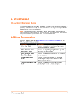
Documentation Visit the Lantronix Web site at www.lantronix.com/support/documentation for the following additional documentation. Document XPort User Guide Description Provides information needed to configure, use, and update the XPort firmware. XPort Universal Demo Board Quick Start Provides - Lantronix XPort | XPort - Integration Guide - Page 7
Specifications The XPort embedded device server is a complete network-enabling solution enclosed within an RJ45 package. This miniature serial-to-Ethernet converter empowers original equipment manufacturers (OEMs) to quickly and easily go to market with networking and web page serving capabilities - Lantronix XPort | XPort - Integration Guide - Page 8
serial interface pins include +3.3V, ground, and reset. The serial signals usually connect to an internal device, such as a UART. For applications requiring an external cable running with RS-232 or RS-422 4-wire and RS-485 2-wire voltage levels, the XPort must interface to a serial transceiver chip - Lantronix XPort | XPort - Integration Guide - Page 9
to DCD of attached device. • Programmable input/output: CP2 can be driven or read through software control, independent of serial port activity. CP3 can be configured as follows: • Flow Terminated Not used 7 Terminated Not Used 8 Terminated SHIELD Chassis ground XPort Integration Guide 9 - Lantronix XPort | XPort - Integration Guide - Page 10
RIGHT LED CONTACT 8 CONTACT 1 SHIELD TAB SHIELD TAB Table 2-3 XPort LED Functions Link LED Left Side Color Meaning Off No Link Amber 10 Mbps Green 100 Mbps Activity LED Right Side Color Meaning Off No Activity Amber Half Duplex Green Full Duplex XPort Integration Guide 10 - Lantronix XPort | XPort - Integration Guide - Page 11
XPort dimensions are shown in the following drawings. Figure 2-4 Front View 18.25 [0.719] 16.25 [0.640] 11.55 [0.455] FRONT VIEW DIMS = mm (in) LEFT LED 7.15 [0.281] RIGHT LED CONTACT 8 14.50 [0.571] 5.85 [0.230] CONTACT 1 4.03 [0.126] 6.35 [0.250] DIMS = mm (in) XPort Integration Guide 11 - Lantronix XPort | XPort - Integration Guide - Page 12
XPort device server device. The XPort shield is considered "chassis ground" and should be separate from "signal ground". ESD near the XPort XPort, it is recommended that the shield not be directly connected to signal GND. The metal shield fingers around the XPort adequate to allow the XPort to work up - Lantronix XPort | XPort - Integration Guide - Page 13
Address* Part Number* Product ID (name) Revision Note: The Part Number* and MAC Address* on the product label will vary according the unit model (XPort-03, XPort-04 or XPort-05). Electrical Specifications CAUTION: Stressing the device Power Reset threshold RESET pin Input low Voltage RESET pin - Lantronix XPort | XPort - Integration Guide - Page 14
/IP, Telnet, ICMP, SNMP, DHCP, BOOTP, TFTP, Auto IP, SMTP, and HTTP 10Base-T and 100Base-TX Link Activity, Full/half duplex. Software generated status & diagnostic signals can optionally drive external LEDs through CP1 & CP3. Internal web server, SNMP (read only) Serial login, Telnet login Password - Lantronix XPort | XPort - Integration Guide - Page 15
3. Diagrams Demo Board Layout Figure 3-1 XPort Demo Board Layout XPort Integration Guide 15 - Lantronix XPort | XPort - Integration Guide - Page 16
3: Diagrams RS-422 4-Wire and RS-485 2-Wire Connection Diagram The following example illustrates a connection between the XPort-485 to an external transceiver IC: Figure 3-2. XPort RS-422 4-Wire and RS-485 2-Wire Connection Diagram XPort Integration Guide 16 - Lantronix XPort | XPort - Integration Guide - Page 17
Information Compliance Information (According to ISO/IEC Guide 22 and EN 45014) Manufacturer's Name & Address: Lantronix 167 Technology Drive, Irvine, CA 92618 USA Declares that the following product: Product Name Model: XPort Embedded Device Server Conforms to the following standards or other - Lantronix XPort | XPort - Integration Guide - Page 18
homogeneous materials for this part is below the Lantronix 167 Technology Drive, Irvine, CA 92618 USA Phone: 949-453-3990 Fax: 949-450-7249 Warranty For details on the Lantronix warranty replacement policy, please go to our Web site at www.lantronix.com/support/warranty. XPort Integration Guide
-
 1
1 -
 2
2 -
 3
3 -
 4
4 -
 5
5 -
 6
6 -
 7
7 -
8
-
9
-
10
-
11
-
12
-
13
-
14
-
15
-
16
-
17
-
18
 |
 |

XPort
Integration Guide
Part Number 900-310
Revision J
February 2013