Lantronix XPort XPort - Integration Guide - Page 5
List of s, List of Tables, XPort RS-422 4-Wire and RS-485 2-Wire Connection Diagram
 |
View all Lantronix XPort manuals
Add to My Manuals
Save this manual to your list of manuals |
Page 5 highlights
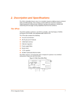
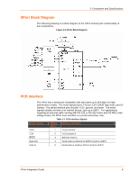
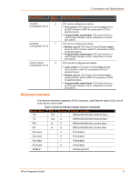
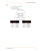
Contents List of Figures Figure 2-1 Side View of the XPort ...7 Figure 2-2 XPort Block Diagram...8 Figure 2-3 XPort LEDs ...10 Figure 2-4 Front View ...11 Figure 2-5 Bottom View ...11 Figure 2-6 Side View ...11 Figure 2-7 PCB Layout ...12 Figure 2-8 Product Label ...13 Figure 3-1. XPort Demo Board Layout 15 Figure 3-2. XPort RS-422 4-Wire and RS-485 2-Wire Connection Diagram 16 List of Tables Table 2-1 PCB Interface Signals ...8 Table 2-2 Ethernet Interface Signals (Industry Standards 9 Table 2-3 XPort LED Functions...10 Table 2-4 Absolute Maximum Ratings 13 Table 2-5 Recommended Operating Conditions 13 Table 2-6 Technical Specification...14 XPort Integration Guide 5
-
 1
1 -
 2
2 -
 3
3 -
 4
4 -
 5
5 -
 6
6 -
 7
7 -
 8
8 -
 9
9 -
 10
10 -
 11
11 -
12
-
13
-
14
-
15
-
16
-
17
-
18
 |
 |

Contents
List of Figures
Figure 2-1 Side View of the XPort
..........................................................................................................
7
Figure 2-2 XPort Block Diagram
.............................................................................................................
8
Figure 2-3 XPort LEDs
.........................................................................................................................
10
Figure 2-4 Front View
...........................................................................................................................
11
Figure 2-5 Bottom View
........................................................................................................................
11
Figure 2-6 Side View
............................................................................................................................
11
Figure 2-7 PCB Layout
.........................................................................................................................
12
Figure 2-8 Product Label
......................................................................................................................
13
Figure 3-1. XPort Demo Board Layout
.................................................................................................
15
Figure 3-2. XPort RS-422 4-Wire and RS-485 2-Wire Connection Diagram
.......................................
16
List of Tables
Table 2-1 PCB Interface Signals
............................................................................................................
8
Table 2-2 Ethernet Interface Signals (Industry Standards)
....................................................................
9
Table 2-3 XPort LED Functions
............................................................................................................
10
Table 2-4 Absolute Maximum Ratings
..................................................................................................
13
Table 2-5 Recommended Operating Conditions
..................................................................................
13
Table 2-6 Technical Specification
.........................................................................................................
14
XPort Integration Guide
5