Lantronix XPort XPort - Integration Guide - Page 9
Ethernet Interface, Signal Name, XPort, Primary Function, Contact - software
 |
View all Lantronix XPort manuals
Add to My Manuals
Save this manual to your list of manuals |
Page 9 highlights
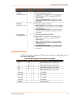
2: Description and Specifications Signal Name CP1/RTS (Configurable Pin 1) XPort Pin # 6 CP2/DTR 7 (Configurable Pin 2) CP3/CTS/DCD 8 (Configurable Pin 3) Primary Function CP1 can be configured as follows: • Flow control: RTS (Request to Send) output driven by DSTni's built-in UART for connection to CTS of attached device. • Programmable input/output: CP1 can be driven or read through software control, independent of serial port activity. CP2 can be configured as follows: • Modem control: DTR (Data Terminal Ready) output driven by DSTni's built-in UART for connection to DCD of attached device. • Programmable input/output: CP2 can be driven or read through software control, independent of serial port activity. CP3 can be configured as follows: • Flow control: CTS (Clear to Send) input read by DSTni's built-in UART for connection to RTS of attached device. • Modem control: DCD (Data Carrier Detect) input read by DSTni's built-in UART for connection to DTR of attached device. • Programmable input/output: CP3 can be driven or read through software control, independent of serial port activity. Ethernet Interface The Ethernet interface magnetics, RJ45 connector, and Ethernet status LEDs are all in the device server shell. Table 2-2 Ethernet Interface Signals (Industry Standards) Signal Name TX+ DIR Contact Primary Function Out 1 Differential Ethernet transmit data + TX- Out 2 Differential Ethernet transmit data - RX+ In 3 Differential Ethernet receive data + RX- In 6 Differential Ethernet receive data - Not used 4 Terminated Not used 5 Terminated Not used 7 Terminated Not Used 8 Terminated SHIELD Chassis ground XPort Integration Guide 9
-
 1
1 -
2
-
3
-
 4
4 -
 5
5 -
 6
6 -
 7
7 -
 8
8 -
 9
9 -
 10
10 -
 11
11 -
 12
12 -
 13
13 -
 14
14 -
15
-
16
-
17
-
18
 |
 |
