Lantronix XPort XPort - Integration Guide - Page 11
Dimensions, Front View - 03
 |
View all Lantronix XPort manuals
Add to My Manuals
Save this manual to your list of manuals |
Page 11 highlights
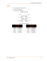
2: Description and Specifications Dimensions The XPort dimensions are shown in the following drawings. Figure 2-4 Front View 18.25 [0.719] 16.25 [0.640] 11.55 [0.455] FRONT VIEW DIMS = mm (in) LEFT LED 7.15 [0.281] RIGHT LED CONTACT 8 14.50 [0.571] 5.85 [0.230] CONTACT 1 4.03 [0.158] 13.50 [0.531] SHIELD TAB 1.27 [0.050] TOLERANCE 0.40 [0.016] .XX+/-0.20[0.008] SHIELD TAB 3.30 [0.130] 1.85 [0.073] 3.25 [0.128] Figure 2-5 Bottom View 8 2 7 1 1.00 [0.039] FRONT Figure 2-6 Side View 33.90 [1.335] INTERFACE PINS SHIELD GROUND 0.60 [0.024] 0.35 [0.014] 10.84 [0.427] TOLERANCE .XX+/-0.20[0.008] 11.90 [0.468] SHIELD TAB 2.54 [0.100] 3.20 [0.126] 6.35 [0.250] DIMS = mm (in) XPort Integration Guide 11
-
 1
1 -
2
-
3
-
4
-
5
-
 6
6 -
 7
7 -
 8
8 -
 9
9 -
 10
10 -
 11
11 -
 12
12 -
 13
13 -
 14
14 -
 15
15 -
 16
16 -
17
-
18
 |
 |

2: Description and Specifications
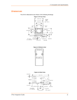
Dimensions
The XPort dimensions are shown in the following drawings.
Figure 2-4 Front View
RIGHT
LED
18.25 [0.719]
16.25 [0.640]
11.55 [0.455]
7.15 [0.281]
CONTACT 1
CONTACT 8
5.85 [0.230]
14.50 [0.571]
4.03 [0.158]
13.50 [0.531]
1.85 [0.073]
3.25 [0.128]
3.30 [0.130]
1.27 [0.050]
0.40 [0.016]
FRONT
VIEW
DIMS = mm (in)
LEFT
LED
SHIELD TAB
SHIELD TAB
TOLERANCE
.XX+/-0.20[0.008]
Figure 2-5 Bottom View
Figure 2-6 Side View
33.90 [1.335]
1.00 [0.039]
0.35 [0.014]
10.84 [0.427]
6.35 [0.250]
2.54 [0.100]
3.20 [0.126]
0.60 [0.024]
FRONT
SHIELD
GROUND
INTERFACE
PINS
DIMS = mm (in)
11.90 [0.468]
SHIELD TAB
TOLERANCE
.XX+/-0.20[0.008]
8
2
7
1
XPort Integration Guide
11