Lantronix XPort XPort - Integration Guide - Page 8
XPort Block Diagram, PCB Interface, Signal Name, XPort, Primary Function
 |
View all Lantronix XPort manuals
Add to My Manuals
Save this manual to your list of manuals |
Page 8 highlights
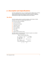
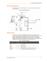
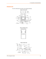
2: Description and Specifications XPort Block Diagram The following drawing is a block diagram of the XPort showing the relationships of the components. Figure 2-2 XPort Block Diagram PCB Interface The XPort has a serial port compatible with data rates up to 920 kbps (in highperformance mode). The serial signals (pins 4-8) are 3.3V CMOS logic level, and 5V tolerant. The serial interface pins include +3.3V, ground, and reset. The serial signals usually connect to an internal device, such as a UART. For applications requiring an external cable running with RS-232 or RS-422 4-wire and RS-485 2-wire voltage levels, the XPort must interface to a serial transceiver chip. Table 2-1 PCB Interface Signals Signal Name XPort Pin # Primary Function GND 1 Circuit ground 3.3V 2 +3.3V power in Reset 3 External reset in Data Out 4 Serial data out (driven by DSTni's built-in UART) Data In 5 Serial data in (read by DSTni's built-in UART) XPort Integration Guide 8
-
 1
1 -
2
-
 3
3 -
 4
4 -
 5
5 -
 6
6 -
 7
7 -
 8
8 -
 9
9 -
 10
10 -
 11
11 -
 12
12 -
 13
13 -
14
-
15
-
16
-
17
-
18
 |
 |
