Lantronix xPico Wi-Fi Freescale Tower System Module xPico Wi-Fi Freescale Towe - Page 10
Power Supply, LEDs, USB, Function, xPico Wi-Fi Pin, Tower Elevator Pin JP5, JP7: 1-2
 |
View all Lantronix xPico Wi-Fi Freescale Tower System Module manuals
Add to My Manuals
Save this manual to your list of manuals |
Page 10 highlights
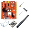
2: Evaluation Kit Power Supply The Lantronix xPico Wi-Fi Freescale Tower System module can be powered from either of the USB connectors on the board. There is circuitry on the xPico Wi-Fi tower module that will convert the 5V input from USB to 3.3V to supply to the rest of the Tower System. This circuitry is turned off if power is detected on the Tower System, and the xPico Wi-Fi module will draw power from the Tower System instead in that case. LEDs The xPico evaluation board includes several LEDs for signal and unit status. The table below lists all of the LEDs and their functions. Note: LEDs 3, 4 and 5 are for future use when the Ethernet is populated. LED LED1/STATUS LED2/LINK JP6: 1-2 LED3/SPEED JP6: 3-4 LED4/ACT JP6: 5-6 LED5/DUP JP6: 7-8 LED6/SERIAL 1 LED7/SERIAL 2 LED8/POWER Table 2-2 LEDs Signals Function Orange: LED blinks with patterns indicating module status. See the xPico Wi-Fi Embedded Device Server User Guide for a full description of the status LED blink patterns Orange: LED is ON when the device is associated with an access point (on the STA interface.) LED is OFF when the device is not associated with an access point. LED is ON when Ethernet is in 100Mbps mode, xPico device with Ethernet only LED blinks when there is activity on the Ethernet port, xPico unit with Ethernet only LED is ON when Ethernet is in half duplex mode, xPico device with Ethernet only Orange: Receive activity Green: Transmit activity Orange: Receive activity Green: Transmit activity Blue: 3.3V Power is on USB There are two USB connectors on the xPico Wi-Fi Tower System module. The J3 connector can optionally be connected to serial port 2 of the xPico Wi-Fi module. See the description for serial port 2. The xPico Wi-Fi has a USB device-side port that can be connected either to the Tower System or to the J2 USB connector on-board. Use jumpers JP5 and JP7 to control where the xPico Wi-Fi USB port is routed. xPico Wi-Fi Pin DDM (24) DDP (22) Tower Elevator Pin (JP5, JP7: 1-2) USB0_DM (A54) USB0_DP (A55) xPico® Wi-Fi® Freescale™ Tower System Module User Guide 10
-
 1
1 -
2
-
3
-
4
-
 5
5 -
 6
6 -
 7
7 -
 8
8 -
 9
9 -
 10
10 -
 11
11 -
 12
12 -
 13
13 -
 14
14 -
 15
15 -
16
-
17
-
18
 |
 |
