Lantronix xPico Wi-Fi Freescale Tower System Module xPico Wi-Fi Freescale Towe - Page 8
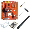
Example Connections on the Freescale Tower System, Lantronix xPico Wi-Fi Module with K60 MCU Board
 |
View all Lantronix xPico Wi-Fi Freescale Tower System Module manuals
Add to My Manuals
Save this manual to your list of manuals |
Page 8 highlights
2: Evaluation Kit Table 2-1 Evaluation Board Connectors, Header and Switches JP Label Function JP1 UUT PWR Connects to 0.301 ohm current sense resistor R1. Measure voltage on JP1 to calculate module power consumption JP2 WAKE Install to use wake-up input and button (xPico Wi-Fi only) JP3 DEFAULT Install to use Default button JP4 RESET Install to use Hardware Reset button JP5 DDP JP7 DDM 1-2: Module USB to Tower System 2-3: Module USB to J2 device port JP6 ETH LED Install jumper 1 to 2 for WLAN status to LED2 JP10 JP11 JP16 JP17 JP18 JP19 J6 TXD2 RXD2 RXD1 TXD1 CTS1 RTS1 CP1-8 1-2: Module serial port 2 to Tower System 2-3: Module serial port 2 to USB to serial FTDI, to J3 1-2: Module connect serial port 1 to tower serial board 2-3: Module connect serial port 1 to tower MCU board Connect CP1-8 (and SPI pins) to Tower System Default Uninstalled Installed Installed Installed 2-3 1-2, 3-4, 5-6 populated; 7-8 not populated 2-3 1-2 Not Installed Example Connections on the Freescale Tower System Lantronix xPico Wi-Fi Module with K60 MCU Board xPico Wi-Fi module: ♦ JP16 through JP19, set to 2-3 ♦ JP5 and JP7 set to 2-3 ♦ Everything else default K60 board: ♦ Make sure J6 is set 1-2 to have the on-board 50MHz feed the peripherals. If you've used this board with the TWR-SER, it would normally be set to 2-3. Lantronix xPico Wi-Fi Module with TWR-SER xPico Wi-Fi module: ♦ JP16 through JP19, set to 1-2 ♦ JP5 and JP7 set to 1-2 xPico® Wi-Fi® Freescale™ Tower System Module User Guide 8
-
 1
1 -
2
-
 3
3 -
 4
4 -
 5
5 -
 6
6 -
 7
7 -
 8
8 -
 9
9 -
 10
10 -
 11
11 -
 12
12 -
 13
13 -
14
-
15
-
16
-
17
-
18
 |
 |
