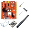
Lantronix xPico Wi-Fi Freescale Tower System Module xPico Wi-Fi Freescale Towe - Page 3
Table of Contents, Introduction, Evaluation Kit
 |
View all Lantronix xPico Wi-Fi Freescale Tower System Module manuals
Add to My Manuals
Save this manual to your list of manuals |
Page 3 highlights
Table of Contents Intellectual Property 2 Warranty 2 Contacts 2 Disclaimer and Revisions 2 Revision History 2 List of Figures 4 List of Tables 4 1. Introduction 5 About this Guide 5 Additional Documentation 5 2. Evaluation Kit 6 xPico Wi-Fi Evaluation Kit Contents 6 Evaluation Board Description 6 Example Connections on the Freescale Tower System 8 Lantronix xPico Wi-Fi Module with K60 MCU Board 8 Lantronix xPico Wi-Fi Module with TWR-SER 8 Serial Port 1 9 Serial Port 2 9 Antenna Port 9 Power Supply 10 LEDs 10 USB 10 SPI and CP 11 Evaluation Board Schematic 12 xPico® Wi-Fi® Freescale™ Tower System Module User Guide 3

xPico® Wi-Fi® Freescale™ Tower System Module User Guide
3
Table of Contents
Intellectual Property _____________________________________________________ 2
Warranty ______________________________________________________________ 2
Contacts ______________________________________________________________ 2
Disclaimer and Revisions _________________________________________________ 2
Revision History ________________________________________________________ 2
List of Figures __________________________________________________________ 4
List of Tables ___________________________________________________________ 4
1.
Introduction
5
About this Guide ________________________________________________________ 5
Additional Documentation _________________________________________________ 5
2.
Evaluation Kit
6
xPico Wi-Fi Evaluation Kit Contents _________________________________________ 6
Evaluation Board Description ______________________________________________ 6
Example Connections on the Freescale Tower System __________________________ 8
Lantronix xPico Wi-Fi Module with K60 MCU Board ______________________ 8
Lantronix xPico Wi-Fi Module with TWR-SER ___________________________ 8
Serial Port 1 ___________________________________________________________ 9
Serial Port 2 ___________________________________________________________ 9
Antenna Port ___________________________________________________________ 9
Power Supply _________________________________________________________ 10
LEDs ________________________________________________________________ 10
USB _________________________________________________________________ 10
SPI and CP ___________________________________________________________ 11
Evaluation Board Schematic ______________________________________________ 12


