Lantronix xPico Wi-Fi Freescale Tower System Module xPico Wi-Fi Freescale Towe - Page 6
Evaluation Kit, xPico Wi-Fi Evaluation Kit Contents, Evaluation Board Description
 |
View all Lantronix xPico Wi-Fi Freescale Tower System Module manuals
Add to My Manuals
Save this manual to your list of manuals |
Page 6 highlights
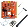
2. Evaluation Kit The Lantronix xPico Wi-Fi Freescale Tower System module (part number TWR-LTRX-XPWK) can help you quickly prototype a design using Wi-Fi with a Freescale microcontroller. xPico Wi-Fi Evaluation Kit Contents ♦ xPico Wi-Fi Module ♦ xPico Wi-Fi Tower Module for Freescale ♦ 2 dBi Swivel Type Antenna and U.FL to RP SMA Cable ♦ Strip Antenna Evaluation Board Description The Lantronix xPico Wi-Fi Tower System module provides a test platform for the Lantronix xPico Wi-Fi device server. The Tower System module uses either 5V power from a USB device port connector or power supplied to the Freescale Tower System. The module board includes all necessary regulators to power the 3.3V xPico module. The Lantronix xPico Wi-Fi Tower System module has the following features: ♦ Two serial ports connected to the Tower System ♦ One mini-type B USB device port connector for 5V input power. This port also has an integrated USB-to-serial converter. The USB-to-serial converter can be connected to the xPico Wi-Fi second serial port via a board jumper setting. ♦ A second mini-type B USB device port is available for direct connection to the xPico Wi-Fi device port, selectable via jumper settings. The jumper settings also allow the xPico WiFi USB device port to connect to the tower board MCU USB port. ♦ LEDs for the xPico Ethernet, WLAN, and System status outputs ♦ Access to all logic level IO signals on the xPico device via header pins for measurements and connection to GPIO lines on the Tower System The figure below shows the xPico Wi-Fi tower board and highlights all of the various connectors and configuration jumpers. The following table lists each of the connectors and jumper headers along with their function. Further description and pin assignments are included in subsequent sections. xPico® Wi-Fi® Freescale™ Tower System Module User Guide 6
-
 1
1 -
 2
2 -
 3
3 -
 4
4 -
 5
5 -
 6
6 -
 7
7 -
 8
8 -
 9
9 -
 10
10 -
 11
11 -
 12
12 -
13
-
14
-
15
-
16
-
17
-
18
 |
 |
