Lantronix xPico Wi-Fi Freescale Tower System Module xPico Wi-Fi Freescale Towe - Page 9
Serial Port 1, Antenna Port, xPico Wi-Fi Pin, Tower Elevator Pin, JP16-19: 2-3
 |
View all Lantronix xPico Wi-Fi Freescale Tower System Module manuals
Add to My Manuals
Save this manual to your list of manuals |
Page 9 highlights
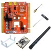
2: Evaluation Kit Serial Port 1 Serial port 1 of the xPico Wi-Fi embedded device server has the signals TX, RX, RTS, and CTS. These signals are connected to serial port 1 on the Tower System. Jumpers JP16 through JP19 allow you to change whether the xPico Wi-Fi module is DTE or DCE. If the xPico Wi-Fi module is connected to an MCU board, the jumpers should be connected 2-3. If using the tower serial board, the jumpers should be 1-2. xPico Wi-Fi Pin RXD1 (7) TXD1 (10) RTS1 (5) CTS1 (16) Tower Elevator Pin JP16-19: 2-3 TXD1 (A44) RXD1 (A43) GPIO9/CTS1 (A9) GPIO1/RTS1 (B21) Tower Elevator Pin JP16-19: 1-2 RXD1 (A43) TXD1 (A44) GPIO1/RTS1 (B21) GPIO9/CTS1 (A9) Serial Port 2 Serial port 2 of the xPico Wi-Fi device has the signals TX and RX. These signals go through jumpers JP10 and JP11. There are two options where this serial port can go. If jumpers JP10 and JP11 are 1-2, then the serial port is connected to serial port 0 on the Tower System. If the jumpers are 2-3, then serial port 2 from the xPico Wi-Fi unit does not go to the Tower System, but instead is routed to an on-board USB to serial converter, which then connects to USB connector J3 on the board. xPico Wi-Fi Pin Tower Elevator Pin (JP10, JP11: 1-2) RXD2 (23) TXD0 (A42) TXD2 (25) RXD0 (A41) In order to access the unit through the J3 USB port, you will need to install the USB-to-serial VCP driver from FTDI on your PC. It is available in the installation directory of Lantronix® DeviceInstaller™ 4.3.0.2 and later versions, for installation. It can also be obtained from the FTDI website provided below. Once installed, you will be able to view the xPico boot messages as well as provide command inputs through any PC terminal program, such as Tera Term. Download FTDI USB-to-serial drivers at this website: http://www.ftdichip.com/Drivers/VCP.htm Antenna Port The xPico Wi-Fi tower board includes a bracket for mounting the U.FL to reverse polarity SMA RF cable included with the kit. Follow the procedure below when installing the antenna cable. The same procedure applies when using the PCB strip antenna, with the exception that the swivel antenna does not need to be connected to the RF cable. ♦ Attach the U.FL cable to the antenna prior to installing the xPico Wi-Fi module on the J1 socket. ♦ Attach the plastic mounting clip to the module. ♦ Install the module into the socket. ♦ Install the external antenna to the SMA end of the RF cable. Note: Install or remove the antenna connections only while the module is powered off. xPico® Wi-Fi® Freescale™ Tower System Module User Guide 9
-
 1
1 -
2
-
3
-
 4
4 -
 5
5 -
 6
6 -
 7
7 -
 8
8 -
 9
9 -
 10
10 -
 11
11 -
 12
12 -
 13
13 -
 14
14 -
15
-
16
-
17
-
18
 |
 |
