Lenovo E40-30 Laptop Hardware Maintenance Manual - Lenovo E40-xx Notebook - Page 71
Detachtheconnector, Removeonescrew, Remove the finger printer broad in the direction shown by arrow
 |
View all Lenovo E40-30 Laptop manuals
Add to My Manuals
Save this manual to your list of manuals |
Page 71 highlights
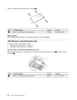
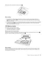
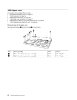
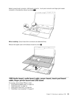
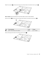
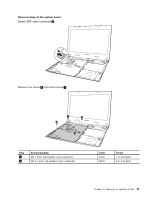
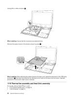
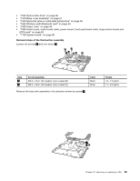
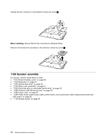
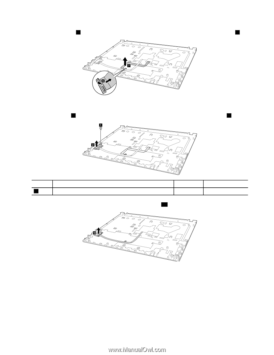
Detach the connector 6 , and then remove the touch pad board cable in the direction shown by arrow 7 . g f When installing: make sure that the touch pad board cable connector is firmly attached. Remove one screw 8 , and then remove the finger printer bracket in the direction shown by arrow 9 . a b Step 8 Screw (quantity) M2 × 3mm, flat-head, nylon-coated (1) Color black Remove the finger printer broad in the direction shown by arrow 10 . Torque 1.0- 1.5 kgfcm j Chapter 10. Removing or replacing a FRU 65
-
 1
1 -
2
-
3
-
4
-
5
-
6
-
7
-
8
-
9
-
10
-
11
-
12
-
13
-
14
-
15
-
16
-
17
-
18
-
19
-
20
-
21
-
22
-
23
-
24
-
25
-
26
-
27
-
28
-
29
-
30
-
31
-
32
-
33
-
34
-
35
-
36
-
37
-
38
-
39
-
40
-
41
-
42
-
43
-
44
-
45
-
46
-
47
-
48
-
49
-
50
-
51
-
52
-
53
-
54
-
55
-
56
-
57
-
58
-
59
-
60
-
61
-
62
-
63
-
64
-
65
-
 66
66 -
 67
67 -
 68
68 -
 69
69 -
 70
70 -
 71
71 -
 72
72 -
 73
73 -
 74
74 -
 75
75 -
 76
76 -
77
-
78
-
79
-
80
-
81
-
82
-
83
-
84
-
85
-
86
-
87
-
88
-
89
-
90
 |
 |
Detachtheconnector
6
,andthenremovethetouchpadboardcableinthedirectionshownbyarrow
7
.
Wheninstalling:
makesurethatthetouchpadboardcableconnectorisfirmlyattached.
Removeonescrew
8
,andthenremovethefingerprinterbracketinthedirectionshownbyarrow
9
.
Step
Screw (quantity)
Color
Torque
8
M2 × 3mm, flat-head, nylon-coated (1)
black
1.0– 1.5 kgfcm
Remove the finger printer broad in the direction shown by arrow
10
.
Chapter 10
.
Removing or replacing a FRU
65