Lenovo E40-30 Laptop Hardware Maintenance Manual - Lenovo E40-xx Notebook - Page 82
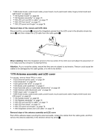
Antenna assembly and LCD cover, cables to be damaged by the cable guides, or a wire to be broken.
 |
View all Lenovo E40-30 Laptop manuals
Add to My Manuals
Save this manual to your list of manuals |
Page 82 highlights
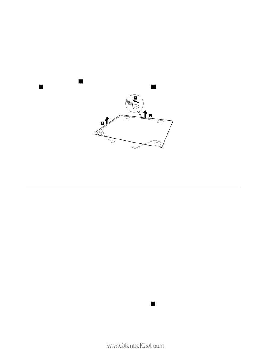
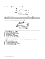
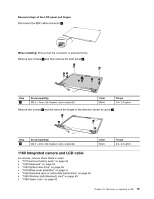
• "1090 Audio board, audio board cable, power board, touch pad board cable, finger printer board and LED board" on page 63 • "1100 System board" on page 66 • "1120 Speaker assembly" on page 70 • "1130 LCD unit and DC-in cable" on page 71 • "1140 LCD front bezel" on page 73 • "1150 LCD panel and hinges" on page 74 Removal steps of the camera and LCD cable Disconnect the connector 1 , remove the integrated camera from the LCD cover in the direction shown by arrow 2 , and then release the LCD cable from the cable guide 3 . a b c When installing: Stick the integrated camera to the top center of the LCD cover and adjust the placement of it to make sure the connector is attached firmly. Attention: As you route the cables, ensure that they are not subject to any tension. Tension could cause the cables to be damaged by the cable guides, or a wire to be broken. 1170 Antenna assembly and LCD cover For access, remove these FRUs in order: • "1010 External battery pack" on page 54 • "1020 Keyboard" on page 54 • "1030 Optical disk drive" on page 56 • "1040 Base cover assembly" on page 57 • "1050 Hard disk drive or solid-state hybrid drive" on page 58 • "1060 Wireless-LAN /Bluetooth card" on page 60 • "1080 Upper case" on page 62 • "1090 Audio board, audio board cable, power board, touch pad board cable, finger printer board and LED board" on page 63 • "1100 System board" on page 66 • "1120 Speaker assembly" on page 70 • "1130 LCD unit and DC-in cable" on page 71 • "1140 LCD front bezel" on page 73 • "1150 LCD panel and hinges" on page 74 • "1160 Integrated camera and LCD cable" on page 75 Removal steps of the antenna assembly and LCD cover Peel off the adhesive tapes securing the antenna boards, release the cables from the cable guide, and then remove the antenna assembly in the direction shown by arrow 1 . 76 Hardware Maintenance Manual
-
 1
1 -
2
-
3
-
4
-
5
-
6
-
7
-
8
-
9
-
10
-
11
-
12
-
13
-
14
-
15
-
16
-
17
-
18
-
19
-
20
-
21
-
22
-
23
-
24
-
25
-
26
-
27
-
28
-
29
-
30
-
31
-
32
-
33
-
34
-
35
-
36
-
37
-
38
-
39
-
40
-
41
-
42
-
43
-
44
-
45
-
46
-
47
-
48
-
49
-
50
-
51
-
52
-
53
-
54
-
55
-
56
-
57
-
58
-
59
-
60
-
61
-
62
-
63
-
64
-
65
-
66
-
67
-
68
-
69
-
70
-
71
-
72
-
73
-
74
-
75
-
76
-
 77
77 -
 78
78 -
 79
79 -
 80
80 -
 81
81 -
 82
82 -
 83
83 -
 84
84 -
 85
85 -
 86
86 -
 87
87 -
88
-
89
-
90
 |
 |