Lenovo E40-30 Laptop Hardware Maintenance Manual - Lenovo E40-xx Notebook - Page 81
Integrated camera and LCD cable, Removal steps of the LCD panel and hinges, When installing
 |
View all Lenovo E40-30 Laptop manuals
Add to My Manuals
Save this manual to your list of manuals |
Page 81 highlights
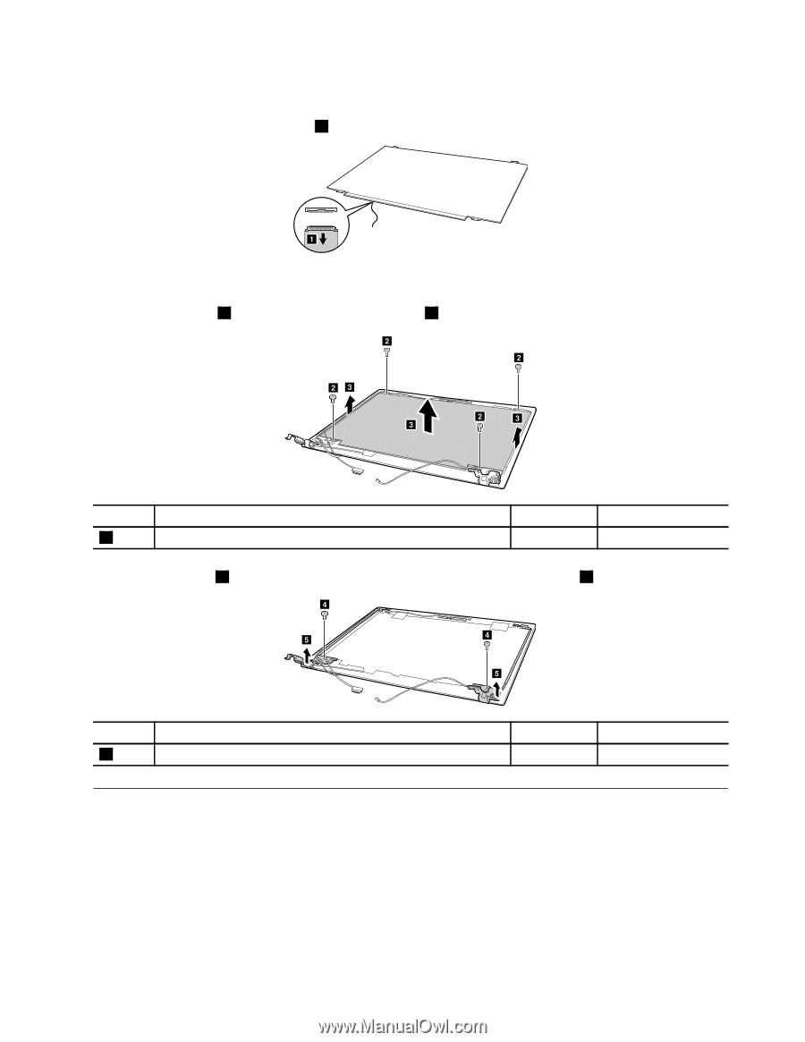
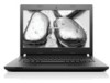
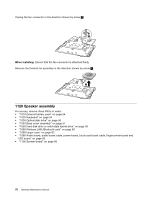
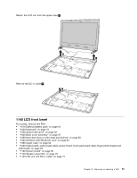
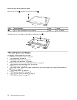
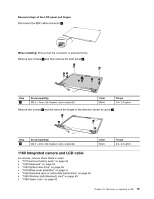
Removal steps of the LCD panel and hinges Disconnect the EDP cable connector 1 . a When installing: Ensure that the connector is attached firmly. Remove four screws 2 and then remove the LCD panel 3 . b b bc b c c Step 2 Screw (quantity) M2.5 × 4mm, flat-headed, nylon-coated (4) Color Black Torque 2.0- 2.5 kgfcm Remove two screws 4 and the remove the hinges in the direction shown by arrow 5 . d e d e Step 4 Screw (quantity) M2.5 × 4mm, flat-headed, nylon-coated (2) 1160 Integrated camera and LCD cable For access, remove these FRUs in order: • "1010 External battery pack" on page 54 • "1020 Keyboard" on page 54 • "1030 Optical disk drive" on page 56 • "1040 Base cover assembly" on page 57 • "1050 Hard disk drive or solid-state hybrid drive" on page 58 • "1060 Wireless-LAN /Bluetooth card" on page 60 • "1080 Upper case" on page 62 Color Black Torque 2.0- 2.5 kgfcm Chapter 10. Removing or replacing a FRU 75
-
 1
1 -
2
-
3
-
4
-
5
-
6
-
7
-
8
-
9
-
10
-
11
-
12
-
13
-
14
-
15
-
16
-
17
-
18
-
19
-
20
-
21
-
22
-
23
-
24
-
25
-
26
-
27
-
28
-
29
-
30
-
31
-
32
-
33
-
34
-
35
-
36
-
37
-
38
-
39
-
40
-
41
-
42
-
43
-
44
-
45
-
46
-
47
-
48
-
49
-
50
-
51
-
52
-
53
-
54
-
55
-
56
-
57
-
58
-
59
-
60
-
61
-
62
-
63
-
64
-
65
-
66
-
67
-
68
-
69
-
70
-
71
-
72
-
73
-
74
-
75
-
 76
76 -
 77
77 -
 78
78 -
 79
79 -
 80
80 -
 81
81 -
 82
82 -
 83
83 -
 84
84 -
 85
85 -
 86
86 -
87
-
88
-
89
-
90
 |
 |