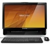
Lenovo IdeaCentre B310 Lenovo IdeaCentre B3 Hardware Maintenance Manual - Page 37
To replace the optical drive
 |
View all Lenovo IdeaCentre B310 manuals
Add to My Manuals
Save this manual to your list of manuals |
Page 37 highlights
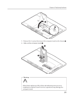
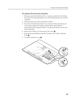
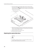
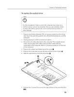
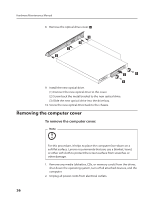
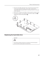
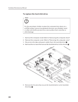
To replace the optical drive Note Chapter 8. Replacing hardware For this procedure, it helps to place the computer face-down on a soft flat surface. Lenovo recommends that you use a blanket, towel, or other soft cloth to protect the screen surface from scratches or other damage. 1. Remove any media (diskettes, CDs, or memory cards) from the drives, shut down the operating system, turn off all attached devices, and the computer. 2. Unplug all power cords from electrical outlets. 3. Disconnect all cables attached to the computer. This includes power cords, input/output (I/O) cables, and any other cables that are connected to the computer. Refer to "Locating connectors on the rear of the computer". 4. Remove the rubber cap that protects the screw. 5. Remove the screw that secures the optical drive to the chassis. 6. Slide the optical drive out of the drive bay. 2 1 3 7. Remove the 2 screws that secure the optical drive to the metal bracket. 35
-
 1
1 -
2
-
3
-
4
-
5
-
6
-
7
-
8
-
9
-
10
-
11
-
12
-
13
-
14
-
15
-
16
-
17
-
18
-
19
-
20
-
21
-
22
-
23
-
24
-
25
-
26
-
27
-
28
-
29
-
30
-
31
-
 32
32 -
 33
33 -
 34
34 -
 35
35 -
 36
36 -
 37
37 -
 38
38 -
 39
39 -
 40
40 -
 41
41 -
 42
42 -
43
-
44
-
45
-
46
-
47
-
48
-
49
-
50
-
51
-
52
-
53
-
54
-
55
-
56
-
57
-
58
-
59
-
60
-
61
-
62
-
63
-
64
 |
 |
