Lenovo IdeaCentre B500 Lenovo IdeaCentre B500 Hardware Maintenance Manual - Page 37
Align the screw holes on the AC inlet to the mounting holes on
 |
View all Lenovo IdeaCentre B500 manuals
Add to My Manuals
Save this manual to your list of manuals |
Page 37 highlights
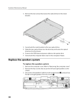
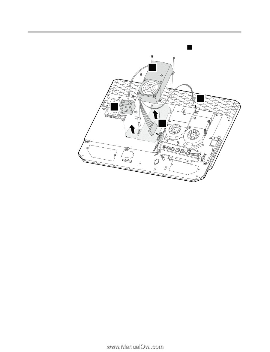
Chapter 8. Replacing hardware 4) Remove the power supply from the chassis 3 . 3 2 1 2 2. Align the screw holes on the new power supply to the mounting holes on the computer chassis. 3. Screw back the four screws on the new power supply. 4. Reconnect all the power supply cables to the drives and the system board. 5. Align the screw holes on the AC inlet to the mounting holes on the computer chassis. 6. Screw back the two screws on the AC inlet. 7. Screw back the computer back cover to the computer chassis. 35
-
 1
1 -
2
-
3
-
4
-
5
-
6
-
7
-
8
-
9
-
10
-
11
-
12
-
13
-
14
-
15
-
16
-
17
-
18
-
19
-
20
-
21
-
22
-
23
-
24
-
25
-
26
-
27
-
28
-
29
-
30
-
31
-
 32
32 -
 33
33 -
 34
34 -
 35
35 -
 36
36 -
 37
37 -
 38
38 -
 39
39 -
 40
40 -
 41
41 -
 42
42 -
43
-
44
-
45
-
46
-
47
-
48
-
49
-
50
-
51
-
52
-
53
-
54
-
55
-
56
-
57
-
58
-
59
-
60
 |
 |
Chapter 8. Replacing hardware
35
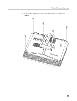
4) Remove the power supply from the chassis
3
.
3
1
2
2
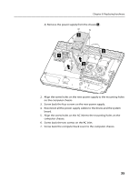
2.
Align the screw holes on the new power supply to the mounting holes
on the computer chassis.
3.
Screw back the four screws on the new power supply.
4.
Reconnect all the power supply cables to the drives and the system
board.
5.
Align the screw holes on the AC inlet to the mounting holes on the
computer chassis.
6.
Screw back the two screws on the AC inlet.
7.
Screw back the computer back cover to the computer chassis.