Lenovo IdeaPad P500 Touch Hardware Maintenance Manual - Page 48
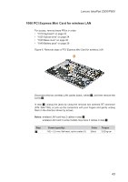
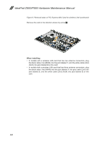
Removal steps of PCI Express Mini Card for wireless LAN continued
 |
View all Lenovo IdeaPad P500 Touch manuals
Add to My Manuals
Save this manual to your list of manuals |
Page 48 highlights
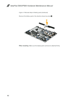
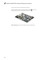
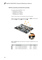
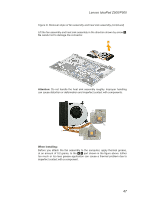
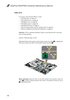
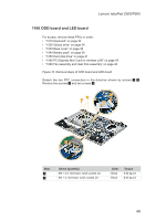
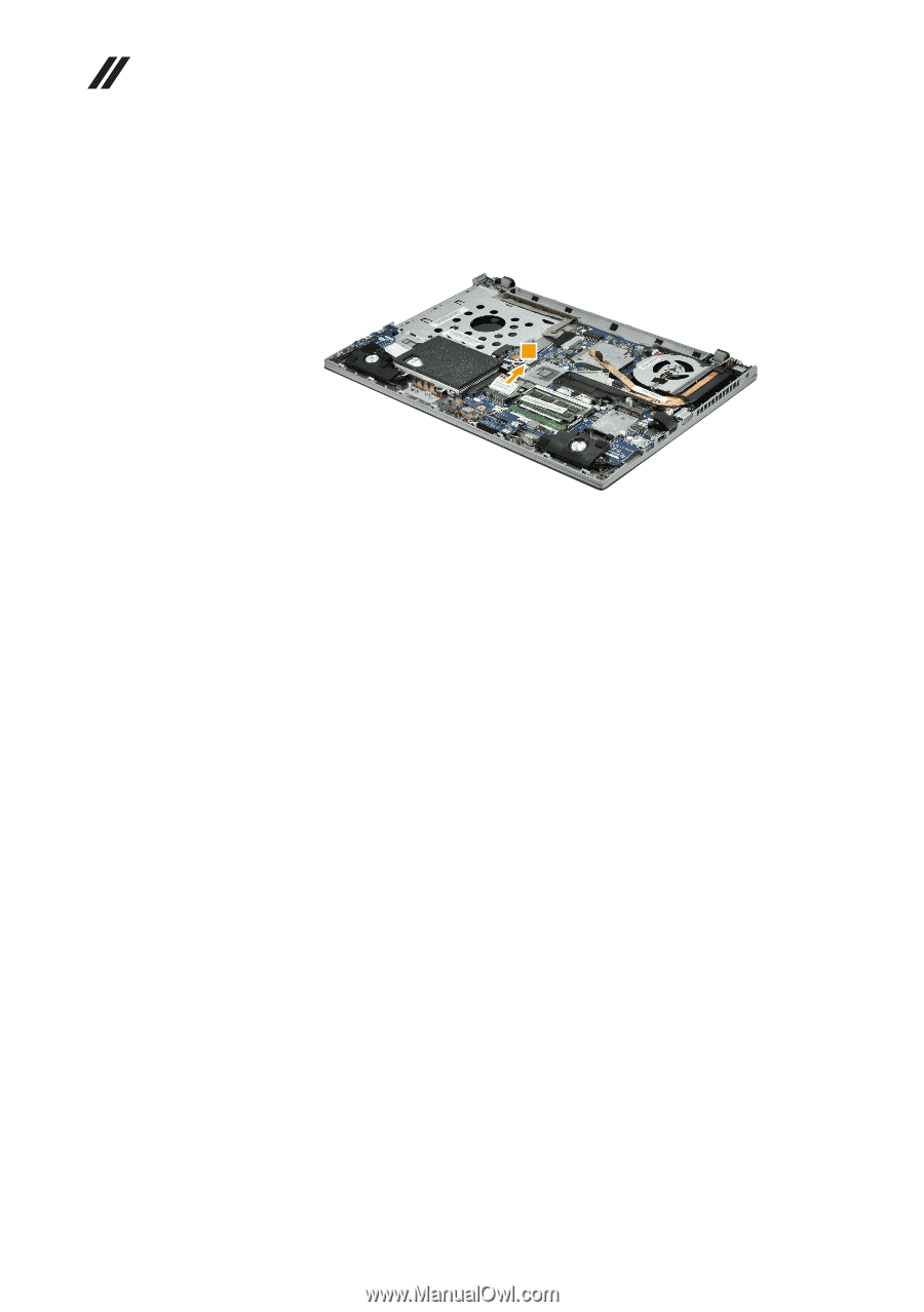
IdeaPad Z500/P500 Hardware Maintenance Manual Figure 6. Removal steps of PCI Express Mini Card for wireless LAN (continued) Remove the card in the direction shown by arrow 3. 3 When installing: •• In models with a wireless LAN card that has two antenna connectors, plug the black cable (1st) (MAIN) into the jack labeled 1, and the white cable (2nd) (AUX) into jack labeled 2 on the card. •• In models with a wireless LAN card that has three antenna connectors, plug the black cable (1st) (MAIN) into the jack labeled 1, the grey cable (3rd) into jack labeled 3, and the white cable (2nd) (AUX) into jack labeled 2 on the card. 44
-
 1
1 -
2
-
3
-
4
-
5
-
6
-
7
-
8
-
9
-
10
-
11
-
12
-
13
-
14
-
15
-
16
-
17
-
18
-
19
-
20
-
21
-
22
-
23
-
24
-
25
-
26
-
27
-
28
-
29
-
30
-
31
-
32
-
33
-
34
-
35
-
36
-
37
-
38
-
39
-
40
-
41
-
42
-
 43
43 -
 44
44 -
 45
45 -
 46
46 -
 47
47 -
 48
48 -
 49
49 -
 50
50 -
 51
51 -
 52
52 -
 53
53 -
54
-
55
-
56
-
57
-
58
-
59
-
60
-
61
-
62
-
63
-
64
-
65
-
66
-
67
-
68
-
69
-
70
-
71
-
72
-
73
-
74
-
75
-
76
-
77
-
78
-
79
-
80
-
81
-
82
-
83
-
84
-
85
-
86
-
87
-
88
-
89
-
90
 |
 |
44
IdeaPad Z500/P500 Hardware Maintenance Manual
Figure 6. Removal steps of PCI Express Mini Card for wireless LAN (continued)
Remove the card in the direction shown by arrow
3
.
3
When installing:
In models with a wireless LAN card that has two antenna connectors, plug
•
the black cable (1st) (MAIN) into the jack labeled
1
, and the white cable (2nd)
(AUX) into jack labeled
2
on the card.
In models with a wireless LAN card that has three antenna connectors, plug
•
the black cable (1st) (MAIN) into the jack labeled
1
, the grey cable (3rd) into
jack labeled
3
, and the white cable (2nd) (AUX) into jack labeled
2
on the
card.