Lenovo IdeaPad P500 Touch Hardware Maintenance Manual - Page 58
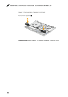
Removal steps of system board continued, Remove
 |
View all Lenovo IdeaPad P500 Touch manuals
Add to My Manuals
Save this manual to your list of manuals |
Page 58 highlights
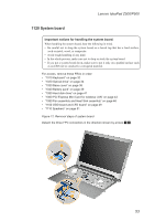
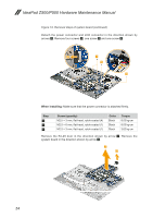
IdeaPad Z500/P500 Hardware Maintenance Manual Figure 12. Removal steps of system board (continued) Detach the power connector and LCD connector in the direction shown by arrows 3. Remove four screws 4, one screw 5 and one screw 6. 3 4 5 3 6 When installing: Make sure that the power connector is attached firmly. Step 4 5 6 Screw (quantity) M2.5 × 3 mm, flat-head, nylok-coated (4) M2.5 × 6 mm, flat-head, nylok-coated (1) M2.5 × 3 mm, flat-head, nylok-coated (1) Color Black Black Black Torque 8.03 kg-cm 8.03 kg-cm 3.62 kg-cm Remove the RJ-45 door in the direction shown by arrow 7. Remove the system board in the direction shown by arrow 8. 8 7 54
-
 1
1 -
2
-
3
-
4
-
5
-
6
-
7
-
8
-
9
-
10
-
11
-
12
-
13
-
14
-
15
-
16
-
17
-
18
-
19
-
20
-
21
-
22
-
23
-
24
-
25
-
26
-
27
-
28
-
29
-
30
-
31
-
32
-
33
-
34
-
35
-
36
-
37
-
38
-
39
-
40
-
41
-
42
-
43
-
44
-
45
-
46
-
47
-
48
-
49
-
50
-
51
-
52
-
 53
53 -
 54
54 -
 55
55 -
 56
56 -
 57
57 -
 58
58 -
 59
59 -
 60
60 -
 61
61 -
 62
62 -
 63
63 -
64
-
65
-
66
-
67
-
68
-
69
-
70
-
71
-
72
-
73
-
74
-
75
-
76
-
77
-
78
-
79
-
80
-
81
-
82
-
83
-
84
-
85
-
86
-
87
-
88
-
89
-
90
 |
 |

54
IdeaPad Z500/P500 Hardware Maintenance Manual
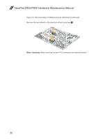
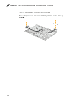
Figure 12. Removal steps of system board (continued)
Detach the power connector and LCD connector in the direction shown by
arrows
3
. Remove four screws
4
, one screw
5
and one screw
6
.
4
5
6
3
3
When installing:
Make sure that the power connector is attached firmly.
Step
Screw (quantity)
Color
Torque
4
M2.5 × 3 mm, flat-head, nylok-coated (4)
Black
8.03 kg-cm
5
M2.5 × 6 mm, flat-head, nylok-coated (1)
Black
8.03 kg-cm
6
M2.5 × 3 mm, flat-head, nylok-coated (1)
Black
3.62 kg-cm
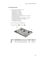
Remove the RJ-45 door in the direction shown by arrow
7
. Remove the
system board in the direction shown by arrow
8
.
7
8