Lenovo IdeaPad P500 Touch Hardware Maintenance Manual - Page 64
LCD panel and hinges, 1120 System board
 |
View all Lenovo IdeaPad P500 Touch manuals
Add to My Manuals
Save this manual to your list of manuals |
Page 64 highlights
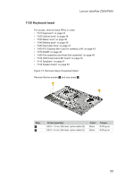
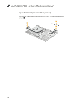
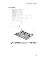
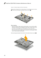
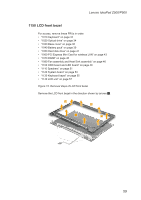
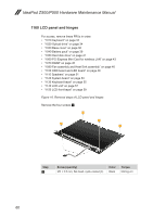
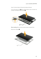
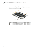
IdeaPad Z500/P500 Hardware Maintenance Manual 1160 LCD panel and hinges For access, remove these FRUs in order: •• "1010 Keyboard" on page 32 •• "1020 Optical drive" on page 34 •• "1030 Base cover" on page 36 •• "1040 Battery pack" on page 39 •• "1050 Hard disk drive" on page 41 •• "1060 PCI Express Mini Card for wireless LAN" on page 43 •• "1070 DIMM" on page 45 •• "1080 Fan assembly and Heat Sink assembly" on page 46 •• "1100 ODD board and LED board" on page 49 •• "1110 Speakers" on page 51 •• "1120 System board" on page 53 •• "1130 Keyboard bezel" on page 55 •• "1140 LCD unit" on page 57 •• "1150 LCD front bezel" on page 59 Figure 16. Removal steps of LCD panel and hinges Remove the four screws 1. 1 1 1 1 Step 1 Screw (quantity) M2 × 2.5 mm, flat-head, nylok-coated (4) Color Black Torque 3.62 kg-cm 60
-
 1
1 -
2
-
3
-
4
-
5
-
6
-
7
-
8
-
9
-
10
-
11
-
12
-
13
-
14
-
15
-
16
-
17
-
18
-
19
-
20
-
21
-
22
-
23
-
24
-
25
-
26
-
27
-
28
-
29
-
30
-
31
-
32
-
33
-
34
-
35
-
36
-
37
-
38
-
39
-
40
-
41
-
42
-
43
-
44
-
45
-
46
-
47
-
48
-
49
-
50
-
51
-
52
-
53
-
54
-
55
-
56
-
57
-
58
-
 59
59 -
 60
60 -
 61
61 -
 62
62 -
 63
63 -
 64
64 -
 65
65 -
 66
66 -
 67
67 -
 68
68 -
 69
69 -
70
-
71
-
72
-
73
-
74
-
75
-
76
-
77
-
78
-
79
-
80
-
81
-
82
-
83
-
84
-
85
-
86
-
87
-
88
-
89
-
90
 |
 |
