Lenovo IdeaPad U260 Lenovo IdeaPad U260 Hardware Maintenance Manual - Page 50
Fan assembly and Heat Sink assembly, Make sure that the fan connector is attached firmly to
 |
View all Lenovo IdeaPad U260 manuals
Add to My Manuals
Save this manual to your list of manuals |
Page 50 highlights
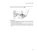
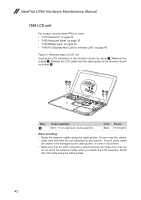
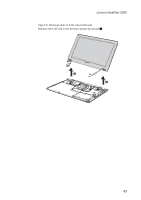
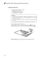
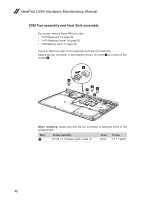
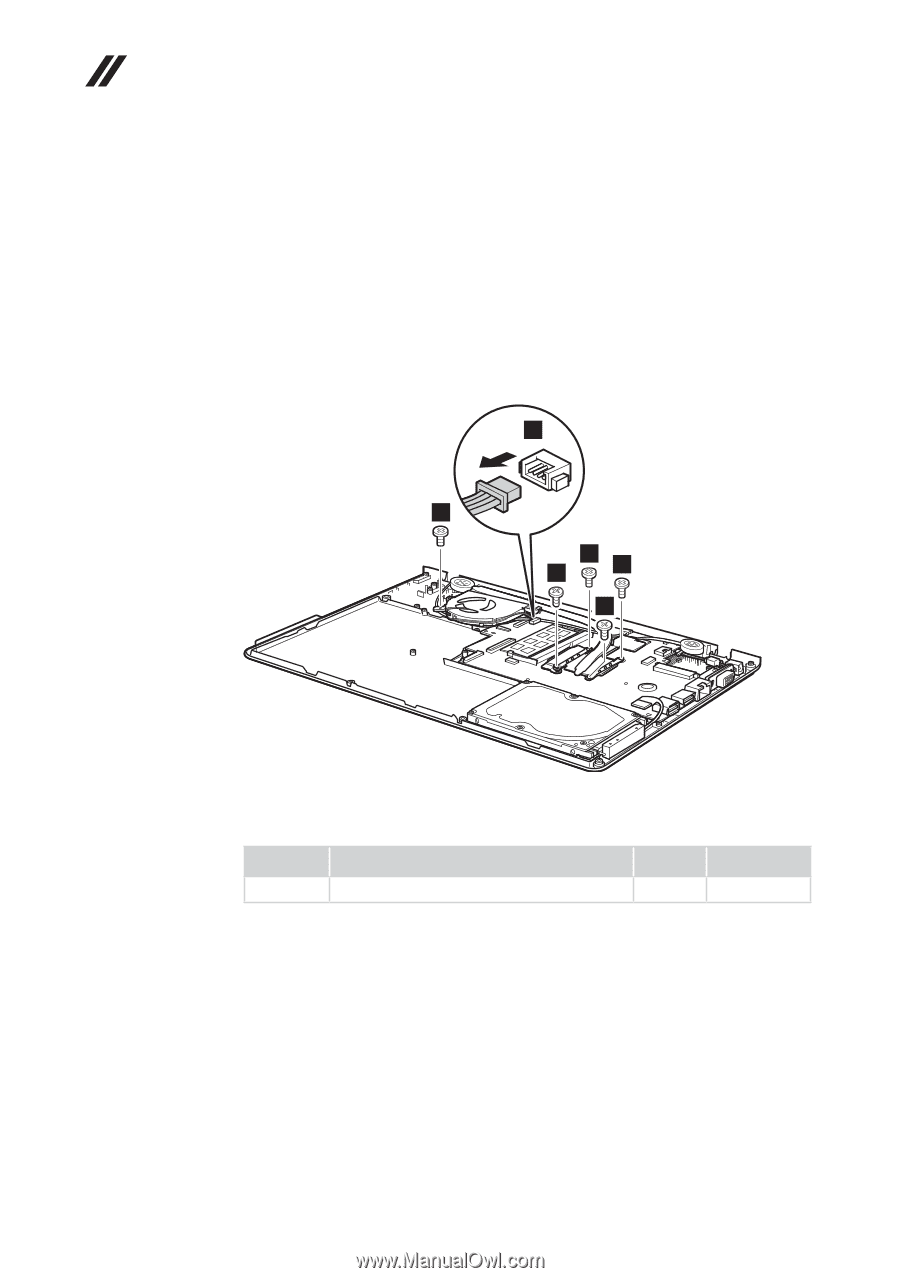
IdeaPad U260 Hardware Maintenance Manual 1080 Fan assembly and Heat Sink assembly For access, remove these FRUs in order: •• "1010 Keyboard" on page 34 •• "1020 Keyboard bezel" on page 35 •• "1030 Battery pack" on page 39 Figure 8. Removal steps of fan assembly and heat sink assembly Detach the fan connector in the direction shown by arrow 1 and remove five screws 2. 1 2 2 2 2 2 When installing: Make sure that the fan connector is attached firmly to the system board. Step 2 Screw (quantity) M1.98 × 3, flat-head, nylok-coated (5) Color White Torque 1.0~1.5 kgfcm 46
-
 1
1 -
2
-
3
-
4
-
5
-
6
-
7
-
8
-
9
-
10
-
11
-
12
-
13
-
14
-
15
-
16
-
17
-
18
-
19
-
20
-
21
-
22
-
23
-
24
-
25
-
26
-
27
-
28
-
29
-
30
-
31
-
32
-
33
-
34
-
35
-
36
-
37
-
38
-
39
-
40
-
41
-
42
-
43
-
44
-
 45
45 -
 46
46 -
 47
47 -
 48
48 -
 49
49 -
 50
50 -
 51
51 -
 52
52 -
 53
53 -
 54
54 -
 55
55 -
56
-
57
-
58
-
59
-
60
-
61
-
62
-
63
-
64
-
65
-
66
-
67
-
68
-
69
-
70
-
71
-
72
-
73
-
74
-
75
-
76
-
77
 |
 |
46
IdeaPad U260 Hardware Maintenance Manual
1080 Fan assembly and Heat Sink assembly
For access, remove these FRUs in order:
•
“1010 Keyboard” on page 34
•
“1020 Keyboard bezel” on page 35
•
“1030 Battery pack” on page 39
Figure 8. Removal steps of fan assembly and heat sink assembly
Detach the fan connector in the direction shown by arrow
1
and remove five
screws
2
.
2
2
2
2
2
1
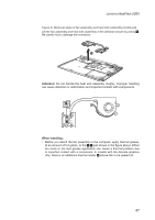
When installing:
Make sure that the fan connector is attached firmly to the
system board.
Step
Screw (quantity)
Color
Torque
2
M1.98 × 3, flat-head, nylok-coated (5)
White
1.0~1.5 kgfcm