Lenovo J110 Hardware Maintenance Manual - Page 123
Replacing the front panel card, Completing the FRU replacement
 |
View all Lenovo J110 manuals
Add to My Manuals
Save this manual to your list of manuals |
Page 123 highlights
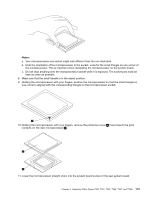
10. Reinstall the hard disk drive. See "Replacing the hard disk drive" on page 114. 11. Reinstall the drive bay assembly. See "Removing and replacing the drive bay assembly" on page 97. 12. Go to "Completing the FRU replacement" on page 117. Replacing the front panel card 1. Remove cover. See "Removing the cover" on page 94. 2. Remove the drive bay assembly. See "Removing and replacing the drive bay assembly" on page 97. 3. Disconnect the front panel assembly cables from the system board. See "Identifying parts on the system board" on page 95. 4. Remove the screw that secures the front panel card assembly to the chassis. 5. Note the front panel assembly cable routing and remove the assembly from the chassis. 6. Route the cable for the new front panel card assembly through the hole in the chassis and to the system board. 7. Install the front panel card assembly into the chassis and secure it with the screw. 8. Connect the front panel assembly cables to the system board. 9. Reinstall the drive bay assembly. See "Removing and replacing the drive bay assembly" on page 97. 10. Go to "Completing the FRU replacement" on page 117. Completing the FRU replacement After replacing FRUs, you need to install any removed parts, replace the cover, and reconnect any cables, including telephone lines and power cords. Also, depending on the FRU that is replaced, you might need to confirm the updated information in the Setup Utility program. Note: When the power cord is first plugged in, the computer might appear to turn on for a few seconds and then turn off. This is a normal sequence to enable the computer to initialize. 1. Ensure that all components have been reassembled correctly and that no tools or loose screws are left inside the computer. 2. Replace the cover and secure it with two screws. Chapter 9. Replacing FRUs (Types 7390, 7391, 7392, 7396, 7397, and 7398) 117
-
 1
1 -
2
-
3
-
4
-
5
-
6
-
7
-
8
-
9
-
10
-
11
-
12
-
13
-
14
-
15
-
16
-
17
-
18
-
19
-
20
-
21
-
22
-
23
-
24
-
25
-
26
-
27
-
28
-
29
-
30
-
31
-
32
-
33
-
34
-
35
-
36
-
37
-
38
-
39
-
40
-
41
-
42
-
43
-
44
-
45
-
46
-
47
-
48
-
49
-
50
-
51
-
52
-
53
-
54
-
55
-
56
-
57
-
58
-
59
-
60
-
61
-
62
-
63
-
64
-
65
-
66
-
67
-
68
-
69
-
70
-
71
-
72
-
73
-
74
-
75
-
76
-
77
-
78
-
79
-
80
-
81
-
82
-
83
-
84
-
85
-
86
-
87
-
88
-
89
-
90
-
91
-
92
-
93
-
94
-
95
-
96
-
97
-
98
-
99
-
100
-
101
-
102
-
103
-
104
-
105
-
106
-
107
-
108
-
109
-
110
-
111
-
112
-
113
-
114
-
115
-
116
-
117
-
 118
118 -
 119
119 -
 120
120 -
 121
121 -
 122
122 -
 123
123 -
 124
124 -
 125
125 -
 126
126 -
 127
127 -
 128
128 -
129
-
130
-
131
-
132
-
133
-
134
-
135
-
136
-
137
-
138
-
139
-
140
-
141
-
142
-
143
-
144
-
145
-
146
-
147
-
148
-
149
-
150
-
151
-
152
-
153
-
154
-
155
-
156
-
157
-
158
-
159
-
160
-
161
-
162
-
163
-
164
-
165
-
166
-
167
-
168
-
169
-
170
-
171
-
172
-
173
-
174
-
175
-
176
-
177
-
178
-
179
-
180
-
181
-
182
-
183
-
184
-
185
-
186
-
187
-
188
-
189
-
190
-
191
-
192
-
193
-
194
-
195
-
196
-
197
-
198
-
199
-
200
 |
 |
