Lenovo J110 Hardware Maintenance Manual - Page 98
Completing the FRU replacement
 |
View all Lenovo J110 manuals
Add to My Manuals
Save this manual to your list of manuals |
Page 98 highlights
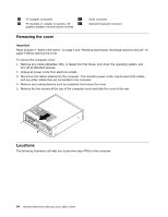
5. Route the new front panel cable through the front of the chassis and Install the screw secures the front panel assembly. 6. Reinstall the bezel. See "Removing and replacing the front bezel" on page 73. 7. Connect the front USB cable and the front audio cable to the system board. See "Identifying parts on the system board" on page 71. 8. Go to "Completing the FRU replacement" on page 92. Completing the FRU replacement After replacing FRUs, you need to install any removed parts, replace the cover, and reconnect any cables, including telephone lines and power cords. Also, depending on the FRU that is replaced, you might need to confirm the updated information in the Setup Utility program. Note: When the power cord is first plugged in, the computer might appear to turn on for a few seconds and then turn off. This is a normal sequence to enable the computer to initialize. 1. Ensure that all components have been reassembled correctly and that no tools or loose screws are left inside the computer. 2. Replace the covers that were removed and secure them with the thumb screws. 3. Reconnect the external cables and power cords to the computer. See "Rear connectors" on page 69. 4. If you have replaced the system board, you must update (flash) the BIOS. See "Flash update procedures" on page 185. 5. Some FRU replacements require the configuration to be updated. See Chapter 6 "Diagnostics, Test and Recovery Information" on page 41. 92 Hardware Maintenance Manual Lenovo 3000 J Series
-
 1
1 -
2
-
3
-
4
-
5
-
6
-
7
-
8
-
9
-
10
-
11
-
12
-
13
-
14
-
15
-
16
-
17
-
18
-
19
-
20
-
21
-
22
-
23
-
24
-
25
-
26
-
27
-
28
-
29
-
30
-
31
-
32
-
33
-
34
-
35
-
36
-
37
-
38
-
39
-
40
-
41
-
42
-
43
-
44
-
45
-
46
-
47
-
48
-
49
-
50
-
51
-
52
-
53
-
54
-
55
-
56
-
57
-
58
-
59
-
60
-
61
-
62
-
63
-
64
-
65
-
66
-
67
-
68
-
69
-
70
-
71
-
72
-
73
-
74
-
75
-
76
-
77
-
78
-
79
-
80
-
81
-
82
-
83
-
84
-
85
-
86
-
87
-
88
-
89
-
90
-
91
-
92
-
 93
93 -
 94
94 -
 95
95 -
 96
96 -
 97
97 -
 98
98 -
 99
99 -
 100
100 -
 101
101 -
 102
102 -
 103
103 -
104
-
105
-
106
-
107
-
108
-
109
-
110
-
111
-
112
-
113
-
114
-
115
-
116
-
117
-
118
-
119
-
120
-
121
-
122
-
123
-
124
-
125
-
126
-
127
-
128
-
129
-
130
-
131
-
132
-
133
-
134
-
135
-
136
-
137
-
138
-
139
-
140
-
141
-
142
-
143
-
144
-
145
-
146
-
147
-
148
-
149
-
150
-
151
-
152
-
153
-
154
-
155
-
156
-
157
-
158
-
159
-
160
-
161
-
162
-
163
-
164
-
165
-
166
-
167
-
168
-
169
-
170
-
171
-
172
-
173
-
174
-
175
-
176
-
177
-
178
-
179
-
180
-
181
-
182
-
183
-
184
-
185
-
186
-
187
-
188
-
189
-
190
-
191
-
192
-
193
-
194
-
195
-
196
-
197
-
198
-
199
-
200
 |
 |
