Lenovo N20 Chromebook Hardware Maintenance Manual - Lenovo N20 Chromebook - Page 40
Remove the LCD module, Step 1. Unplug the LCD cable
 |
View all Lenovo N20 Chromebook manuals
Add to My Manuals
Save this manual to your list of manuals |
Page 40 highlights
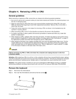
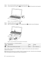
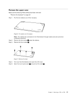
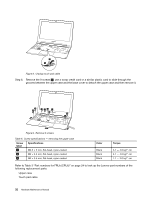
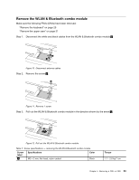
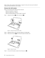
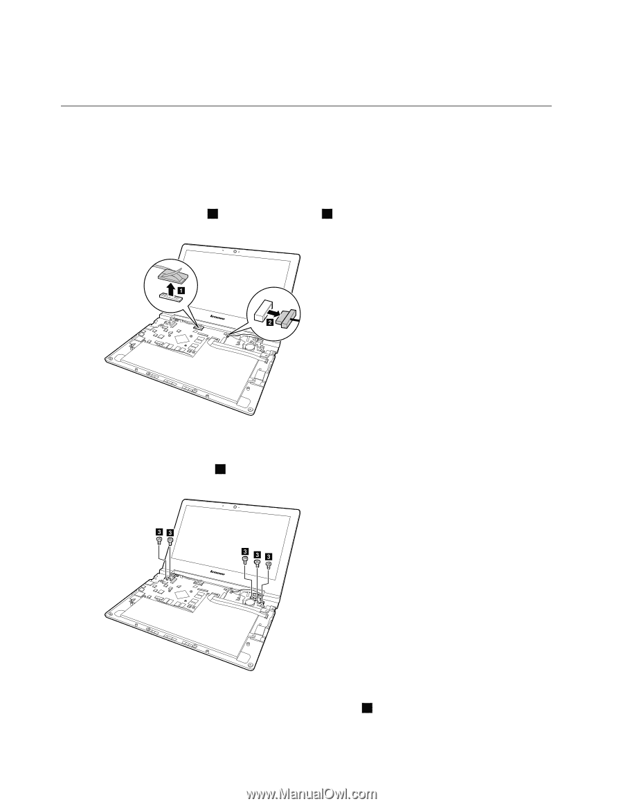
Refer to Table 3 "Part numbers for FRUs (CRUs)" on page 24 to look up the Lenovo part numbers of replacement WLAN & Bluetooth combo modules. Remove the LCD module Make sure the following FRUs (CRUs) have been removed: "Remove the keyboard" on page 29 "Remove the upper case" on page 31 "Remove the WLAN & Bluetooth combo module" on page 33 Step 1. Unplug the LCD cable 1 and the camera cable 2 . a b Figure 13. Unplug the LCD and camera cables Step 2. Release the antenna, LCD, and camera cables out of cable guides. Step 3. Remove the five screws 3 that fix the LCD module to the base cover. cc c cc Figure 14. Remove 5 screws Step 4. Lift up the LCD module to detach it from the base cover 4 . 34 Hardware Maintenance Manual
-
 1
1 -
2
-
3
-
4
-
5
-
6
-
7
-
8
-
9
-
10
-
11
-
12
-
13
-
14
-
15
-
16
-
17
-
18
-
19
-
20
-
21
-
22
-
23
-
24
-
25
-
26
-
27
-
28
-
29
-
30
-
31
-
32
-
33
-
34
-
 35
35 -
 36
36 -
 37
37 -
 38
38 -
 39
39 -
 40
40 -
 41
41 -
 42
42 -
 43
43 -
 44
44 -
 45
45 -
46
-
47
-
48
-
49
-
50
-
51
-
52
-
53
-
54
-
55
-
56
-
57
-
58
-
59
-
60
-
61
-
62
 |
 |
RefertoTable3“PartnumbersforFRUs(CRUs)”onpage24tolookuptheLenovopartnumbersof
replacementWLAN&Bluetoothcombomodules.
Remove the LCD module
MakesurethefollowingFRUs(CRUs)havebeenremoved:
“Removethekeyboard”onpage29
“Removetheuppercase”onpage31
“RemovetheWLAN&Bluetoothcombomodule”onpage33
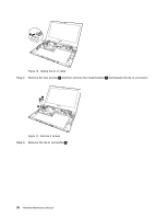
Step 1. Unplug the LCD cable
1
andthecameracable
2
.
Figure13. Unplug the LCD and camera cables
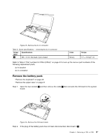
Step 2. Release the antenna, LCD, and camera cables out of cable guides.
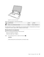
Step 3. Remove the five screws
3
thatfixtheLCDmoduletothebasecover.
Figure14. Remove 5 screws
Step 4. Lift up the LCD module to detach it from the base cover
4
.
34
HardwareMaintenanceManual