Lenovo N20 Chromebook Hardware Maintenance Manual - Lenovo N20 Chromebook - Page 47
Remove the LCD panel, followingreplacementparts, Hinge covers, LCD bezel, RemovetheLCDbezelon
 |
View all Lenovo N20 Chromebook manuals
Add to My Manuals
Save this manual to your list of manuals |
Page 47 highlights
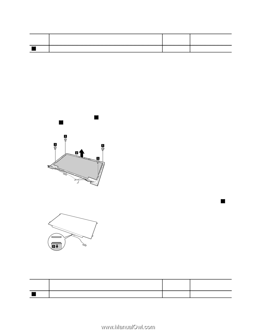
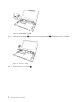
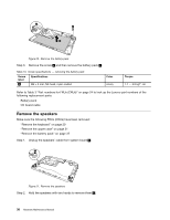
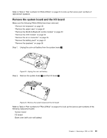
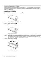
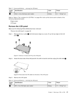
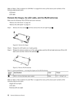
Table 11. Screw specifications - removing the LCD bezel Screw label 2 Specifications M2.5 × 5 mm, flat-head, nylon-coated Color Silvery Torque 3.7 - 4.0 kgf * cm Refer to Table 4 "Part numbers for LCD FRUs" on page 26 to look up the Lenovo part numbers of the following replacement parts: Hinge covers LCD bezel Remove the LCD panel Make sure the following FRUs (CRUs) have been removed: "Remove the LCD bezel" on page 40 Step 1. Remove the four screws 1 ; with the bottom edge as an axis, lift up the top edge of the LCD panel 2 . a a b a a Figure 27. Remove 4 screws and lift up the LCD panel Step 2. Check the back side of the LCD panel for the LCD connector and then unplug the LCD cable 3 . c Figure 28. Disconnect the LCD cable from the back of the LCD panel Step 3. Remove the LCD panel. Table 12. Screw specifications - removing the LCD panel Screw label 1 Specifications M2 × 3 mm, flat-head, nylon-coated Color Silvery Torque 1.7 - 2.0 kgf * cm Chapter 4. Removing a FRU or CRU 41
-
 1
1 -
2
-
3
-
4
-
5
-
6
-
7
-
8
-
9
-
10
-
11
-
12
-
13
-
14
-
15
-
16
-
17
-
18
-
19
-
20
-
21
-
22
-
23
-
24
-
25
-
26
-
27
-
28
-
29
-
30
-
31
-
32
-
33
-
34
-
35
-
36
-
37
-
38
-
39
-
40
-
41
-
 42
42 -
 43
43 -
 44
44 -
 45
45 -
 46
46 -
 47
47 -
 48
48 -
 49
49 -
 50
50 -
 51
51 -
 52
52 -
53
-
54
-
55
-
56
-
57
-
58
-
59
-
60
-
61
-
62
 |
 |