Lenovo NetVista X40 Hardware Maintenance Manual for NetVista 2179 and 6643 sys - Page 39
Chassis, assembly, removal
 |
View all Lenovo NetVista X40 manuals
Add to My Manuals
Save this manual to your list of manuals |
Page 39 highlights
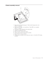
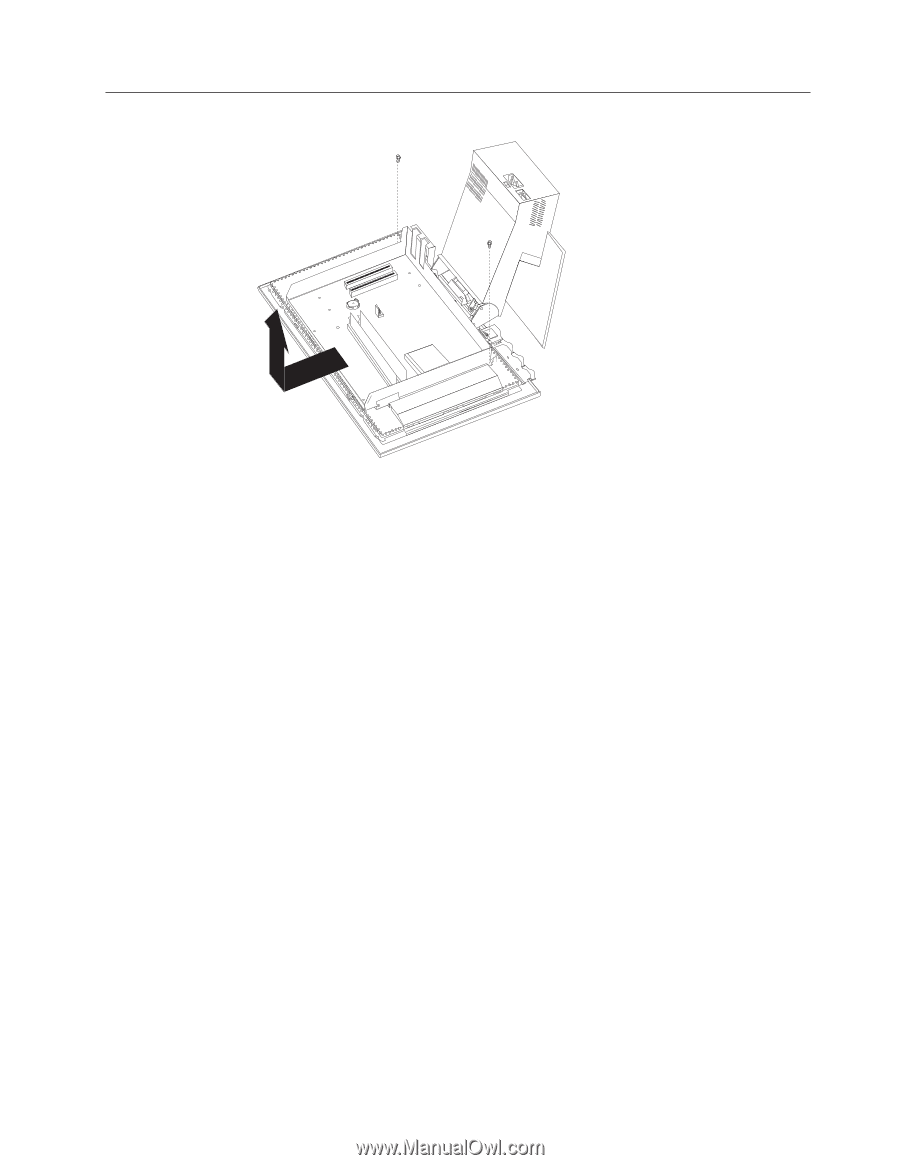
Chassis assembly removal 1. Remove the rear bucket housing, see "Rear bucket housing (rear cover) removal" on page 21. 2. Remove the rear EMC cover assembly, see "Rear EMC cover assembly removal" on page 23. 3. Disconnect all cables attached to the system board. 4. Unplug any installed PCI cards. 5. Remove the nine system board screws. 6. Lift the system board from the chassis assembly. 7. Remove the two screws as shown. 8. Pull the chassis assembly forward, then up to remove it from the LCD housing assembly. Chapter 4. FRU replacements 31
-
 1
1 -
2
-
3
-
4
-
5
-
6
-
7
-
8
-
9
-
10
-
11
-
12
-
13
-
14
-
15
-
16
-
17
-
18
-
19
-
20
-
21
-
22
-
23
-
24
-
25
-
26
-
27
-
28
-
29
-
30
-
31
-
32
-
33
-
 34
34 -
 35
35 -
 36
36 -
 37
37 -
 38
38 -
 39
39 -
 40
40 -
 41
41 -
 42
42 -
 43
43 -
 44
44 -
45
-
46
-
47
-
48
-
49
-
50
-
51
-
52
-
53
-
54
-
55
-
56
-
57
-
58
-
59
-
60
-
61
-
62
-
63
-
64
-
65
-
66
-
67
-
68
-
69
-
70
-
71
-
72
-
73
-
74
-
75
-
76
-
77
-
78
-
79
-
80
-
81
-
82
-
83
-
84
-
85
-
86
-
87
-
88
-
89
-
90
-
91
-
92
-
93
-
94
-
95
-
96
-
97
-
98
-
99
-
100
-
101
-
102
-
103
-
104
-
105
-
106
-
107
-
108
-
109
-
110
-
111
-
112
-
113
-
114
-
115
-
116
-
117
-
118
-
119
-
120
-
121
-
122
-
123
-
124
-
125
-
126
-
127
-
128
 |
 |
Chassis
assembly
removal
1.
Remove
the
rear
bucket
housing,
see
“Rear
bucket
housing
(rear
cover)
removal”
on
page
21.
2.
Remove
the
rear
EMC
cover
assembly,
see
“Rear
EMC
cover
assembly
removal”
on
page
23.
3.
Disconnect
all
cables
attached
to
the
system
board.
4.
Unplug
any
installed
PCI
cards.
5.
Remove
the
nine
system
board
screws.
6.
Lift
the
system
board
from
the
chassis
assembly.
7.
Remove
the
two
screws
as
shown.
8.
Pull
the
chassis
assembly
forward,
then
up
to
remove
it
from
the
LCD
housing
assembly.
Chapter
4.
FRU
replacements
31