Lenovo NetVista Hardware Maintenance Manual (HMM) for NetVista 2271, 6840, and - Page 40
Power supply removal, Signal, Function
 |
View all Lenovo NetVista manuals
Add to My Manuals
Save this manual to your list of manuals |
Page 40 highlights
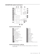
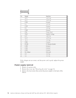
Pin Signal 1 3.3 V 2 3.3 V 3 COM 4 5 V 5 COM 6 5 V 7 COM 8 POK 9 5VSB 10 12 V 11 3.3 V 12 -12 V 13 COM 14 PS-ON 15 COM 16 COM 17 COM 18 No voltage 19 5 V 20 5 V Function +3.3 V dc +3.3 V dc Ground +5 V dc Ground +5 V dc Ground Power Good Standby Voltage +12 V dc +3.3 V dc -12 V dc Ground DC Remote Enable Ground Ground Ground Not used +5 V dc +5 V dc If the voltages are not correct, and the power cord is good, replace the power supply. Power supply removal 1. Remove the power cable. 2. Remove the cover (see "Removing the cover" on page 15). 3. Remove the four screws that secure the power supply to the back of the chassis. 34 Hardware Maintenance Manual A40 Type 6840 A40P Type 6841 A40i Type 2271: IBM NetVista Computer
-
 1
1 -
2
-
3
-
4
-
5
-
6
-
7
-
8
-
9
-
10
-
11
-
12
-
13
-
14
-
15
-
16
-
17
-
18
-
19
-
20
-
21
-
22
-
23
-
24
-
25
-
26
-
27
-
28
-
29
-
30
-
31
-
32
-
33
-
34
-
 35
35 -
 36
36 -
 37
37 -
 38
38 -
 39
39 -
 40
40 -
 41
41 -
 42
42 -
 43
43 -
 44
44 -
 45
45 -
46
-
47
-
48
-
49
-
50
-
51
-
52
-
53
-
54
-
55
-
56
-
57
-
58
-
59
-
60
-
61
-
62
-
63
-
64
-
65
-
66
-
67
-
68
-
69
-
70
-
71
-
72
-
73
-
74
-
75
-
76
-
77
-
78
-
79
-
80
-
81
-
82
-
83
-
84
-
85
-
86
-
87
-
88
-
89
-
90
-
91
-
92
-
93
-
94
-
95
-
96
-
97
-
98
-
99
-
100
-
101
-
102
-
103
-
104
-
105
-
106
-
107
-
108
-
109
-
110
-
111
-
112
-
113
-
114
-
115
-
116
-
117
-
118
-
119
-
120
-
121
-
122
-
123
-
124
-
125
-
126
-
127
-
128
-
129
-
130
-
131
-
132
-
133
-
134
-
135
-
136
-
137
-
138
-
139
-
140
-
141
-
142
-
143
-
144
-
145
-
146
-
147
-
148
 |
 |

Pin
Signal
Function
1
3.3 V
+3.3 V dc
2
3.3 V
+3.3 V dc
3
COM
Ground
4
5 V
+5 V dc
5
COM
Ground
6
5 V
+5 V dc
7
COM
Ground
8
POK
Power Good
9
5VSB
Standby Voltage
10
12 V
+12 V dc
11
3.3 V
+3.3 V dc
12
-12 V
-12 V dc
13
COM
Ground
14
PS-ON
DC Remote Enable
15
COM
Ground
16
COM
Ground
17
COM
Ground
18
No voltage
Not used
19
5 V
+5 V dc
20
5 V
+5 V dc
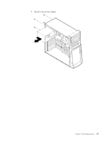
If the voltages are not correct, and the power cord is good, replace the power
supply.
Power supply removal
1.
Remove the power cable.
2.
Remove the cover (see “Removing the cover” on page 15).
3.
Remove the four screws that secure the power supply to the back of the
chassis.
34
Hardware Maintenance Manual A40 Type 6840 A40P Type 6841 A40i Type 2271: IBM NetVista Computer