Lenovo PC 300PL Technical Information Manual for IBM PC300GL (Type 6563, 6564, - Page 19
Parallel port, Keyboard and mouse ports, Table 4., Serial port assignments, Port assignment
 |
View all Lenovo PC 300PL manuals
Add to My Manuals
Save this manual to your list of manuals |
Page 19 highlights
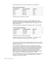
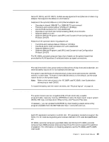
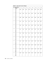
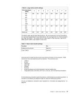
The following figure shows the serial port assignments in the configuration. Table 4. Serial port assignments Port assignment Address range (hex) Serial 1 03F8-03FF Serial 2 02F8-02FF Serial 3 03E8-03FF Serial 4 O2E8-027F IRQ level IRQ4 IRQ3 IRQ4 IRQ13 The default setting for the serial port is COM1. Parallel port Integrated in the system board is support for extended capabilities port (ECP), enhanced parallel port (EPP), and standard parallel port (SPP) modes. The modes of operation are selected through the Configuration/Setup Utility program with the default mode set to SPP. The following figure shows the parallel port assignments used in the configuration. Table 5. Parallel port assignments Port assignment Address range (hex) Parallel 1 03BC-03BE Parallel 2 0378-037F Parallel 3 0278-03FF IRQ level IRQ7 IRQ5 IRQ5 The default setting for the parallel port is Parallel 1. The system board has one connector for the parallel port. For information on the connector pin assignments, see "Parallel port connector" on page 46. Keyboard and mouse ports A general purpose 8-bit microcontroller, 8042AH compatible, controls the mouse and keyboard subsystem. The controller consists of 256 bytes of data memory and 2 KB of read-only memory (ROM). The controller has two logical devices: one controls the keyboard and the other controls the mouse. The keyboard has two fixed I/O addresses, a fixed IRQ line, and can operate without the mouse. The mouse cannot operate without the keyboard because, although it has a fixed IRQ line, the mouse relies on the addresses of the keyboard for operation. For the keyboard and mouse interfaces, no resource assignments are given in the system memory addresses or DMA channels. For information on the resource assignments, see "Input/output address map" on page 48 and "Appendix C. IRQ and DMA channel assignments," on page 53. The system board has one connector for the keyboard port and one connector for the mouse port. For information on the connector pin assignments, see "Mouse and keyboard port connectors" on page 45. 12 PC 300 GL and 300 PL
-
 1
1 -
2
-
3
-
4
-
5
-
6
-
7
-
8
-
9
-
10
-
11
-
12
-
13
-
 14
14 -
 15
15 -
 16
16 -
 17
17 -
 18
18 -
 19
19 -
 20
20 -
 21
21 -
 22
22 -
 23
23 -
 24
24 -
25
-
26
-
27
-
28
-
29
-
30
-
31
-
32
-
33
-
34
-
35
-
36
-
37
-
38
-
39
-
40
-
41
-
42
-
43
-
44
-
45
-
46
-
47
-
48
-
49
-
50
-
51
-
52
-
53
-
54
-
55
-
56
-
57
-
58
-
59
-
60
-
61
-
62
-
63
-
64
-
65
-
66
-
67
-
68
-
69
 |
 |
