Lenovo PC 300PL Technical Information Manual for IBM PC300GL (Type 6563, 6564, - Page 38
System compatibility, Hardware compatibility, Hardware interrupts
 |
View all Lenovo PC 300PL manuals
Add to My Manuals
Save this manual to your list of manuals |
Page 38 highlights
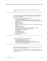
Chapter 6. System compatibility This chapter discusses some of the hardware, software, and BIOS compatibility issues for the computer. See the Compatibility Report under, "Related publications" on page vii for a list of compatible hardware and software options. Hardware compatibility This section discusses hardware, software, and BIOS compatibility that must be considered when designing application programs. The functional interfaces are compatible with the following interfaces: • Intel 8259 interrupt controllers (edge-triggered mode) • National Semiconductor NS16450 and NS126550A serial communications controllers • Motorola MC146818 Time of Day Clock command and status (CMOS reorganized) • Intel 8254 timer, driven from a 1.193 MHz clock (channels 0, 1, and 2) • Intel 8237 DMA controller, except for the Command and Request registers and the Rotate and Mask functions; the Mode register is partially supported • Intel 8272 or 82077 diskette drive controllers • Intel 8042 keyboard controller at address hex 0060 and hex 0064 • All video standards using VGA, EGA, CGA, MDA, and Hercules modes • Parallel printer ports (Parallel 1, Parallel 2, and Parallel 3) in compatibility mode Use this information to develop application programs. Whenever possible, use the BIOS as an interface to hardware to provide maximum compatibility and portability of applications among systems. Hardware interrupts Hardware interrupts are level-sensitive for PCI interrupts. The interrupt controller clears its in-service register bit when the interrupt routine sends and End-of-Interrupt (EOI) command to the controller. The EOI command is sent regardless of whether the incoming interrupt request to the controller is active or inactive. The interrupt-in-progress latch is readable at an I/O-address bit position. This latch is read during the interrupt service routine and might be reset by the read operation or it might require an explicit reset. Note: For performance and latency considerations, designers might want to limit the number of devices sharing an interrupt level. With level-sensitive interrupts, the interrupt controller requires that the interrupt request be inactive at the time the EOI command is sent; otherwise, a new interrupt request will be detected. To avoid this, a level-sensitive interrupt handler must clear the interrupt condition (usually by a read or write operation to an I/O port on the device causing the interrupt). After processing the interrupt, the interrupt handler: 1. Clears the interrupt 2. Waits one I/O delay © Copyright IBM Corp. 2000 31
-
 1
1 -
2
-
3
-
4
-
5
-
6
-
7
-
8
-
9
-
10
-
11
-
12
-
13
-
14
-
15
-
16
-
17
-
18
-
19
-
20
-
21
-
22
-
23
-
24
-
25
-
26
-
27
-
28
-
29
-
30
-
31
-
32
-
 33
33 -
 34
34 -
 35
35 -
 36
36 -
 37
37 -
 38
38 -
 39
39 -
 40
40 -
 41
41 -
 42
42 -
 43
43 -
44
-
45
-
46
-
47
-
48
-
49
-
50
-
51
-
52
-
53
-
54
-
55
-
56
-
57
-
58
-
59
-
60
-
61
-
62
-
63
-
64
-
65
-
66
-
67
-
68
-
69
 |
 |
