Lenovo S5000 S5000-F / S5000-H Hardware Maintenance Manual - Page 39
Rear frame, on the rear frame.
 |
View all Lenovo S5000 manuals
Add to My Manuals
Save this manual to your list of manuals |
Page 39 highlights
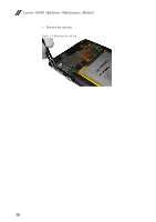
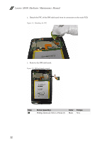
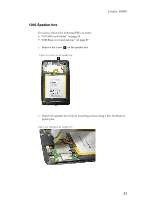
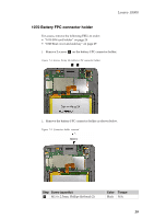
1050 Rear frame For access, remove the following FRUs in order: • "1010 SIM card holder" on page 28 • "1020 Rear cover and side key" on page 29 • "1030 SIM sub board" on page 31 1. Remove 9 screws a on the rear frame. Figure 5-1. Screws on the rear frame Lenovo S5000 2. Insert a guitar pick into the joint between the main body and rear frame from the front side of the computer to unlock the rear frame from the computer. Figure 5-2. Unlocking the rear frame 3. Slowly detach the entire rear frame from the main body. 35
-
 1
1 -
2
-
3
-
4
-
5
-
6
-
7
-
8
-
9
-
10
-
11
-
12
-
13
-
14
-
15
-
16
-
17
-
18
-
19
-
20
-
21
-
22
-
23
-
24
-
25
-
26
-
27
-
28
-
29
-
30
-
31
-
32
-
33
-
 34
34 -
 35
35 -
 36
36 -
 37
37 -
 38
38 -
 39
39 -
 40
40 -
 41
41 -
 42
42 -
 43
43 -
 44
44 -
45
-
46
-
47
-
48
-
49
-
50
-
51
-
52
-
53
-
54
-
55
-
56
-
57
-
58
-
59
-
60
 |
 |

Lenovo S5000
35
1050 Rear frame
For access, remove the following FRUs in order:
•
“1010 SIM card holder” on page 28
•
“1020 Rear cover and side key” on page 29
•
“1030 SIM sub board” on page 31
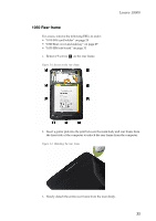
1.
Remove 9 screws
on the rear frame.
Figure 5-1. Screws on the rear frame
2.
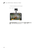
Insert a guitar pick into the joint between the main body and rear frame from
the front side of the computer to unlock the rear frame from the computer.
Figure 5-2. Unlocking the rear frame
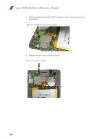
3.
Slowly detach the entire rear frame from the main body.
a