Lenovo S5000 S5000-F / S5000-H Hardware Maintenance Manual - Page 52
Detaching the TP FPC, Main PCBA removed
 |
View all Lenovo S5000 manuals
Add to My Manuals
Save this manual to your list of manuals |
Page 52 highlights
Lenovo S5000 Hardware Maintenance Manual 6. Detach the TP FPC from its connector on the main PCBA. Figure 11-6. Detaching the TP FPC 7. Slowly remove the main PCBA from its seating surface. Figure 11-7. Main PCBA removed Step Screw (quantity) a M1.4 x 2.5mm, Phillips flat-head (2) Color Torque Black N/A 48
-
 1
1 -
2
-
3
-
4
-
5
-
6
-
7
-
8
-
9
-
10
-
11
-
12
-
13
-
14
-
15
-
16
-
17
-
18
-
19
-
20
-
21
-
22
-
23
-
24
-
25
-
26
-
27
-
28
-
29
-
30
-
31
-
32
-
33
-
34
-
35
-
36
-
37
-
38
-
39
-
40
-
41
-
42
-
43
-
44
-
45
-
46
-
 47
47 -
 48
48 -
 49
49 -
 50
50 -
 51
51 -
 52
52 -
 53
53 -
 54
54 -
 55
55 -
 56
56 -
 57
57 -
58
-
59
-
60
 |
 |

Lenovo S5000 Hardware Maintenance Manual
48
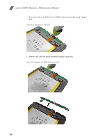
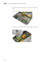
6.
Detach the TP FPC from its connector on the main PCBA.
Figure 11-6. Detaching the TP FPC
7.
Slowly remove the main PCBA from its seating surface.
Figure 11-7. Main PCBA removed
Step
Screw (quantity)
Color
Torque
M1.4 x 2.5mm, Phillips flat-head (2)
Black
N/A
a