Lenovo ThinkPad A21e Hardware Maintenance Manual for ThinkPad A22m (wireless m - Page 108
Route the cable under LCD flexible cable, alongside the LCD.
 |
View all Lenovo ThinkPad A21e manuals
Add to My Manuals
Save this manual to your list of manuals |
Page 108 highlights
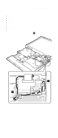
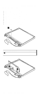
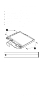
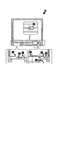
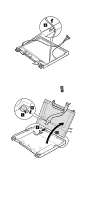
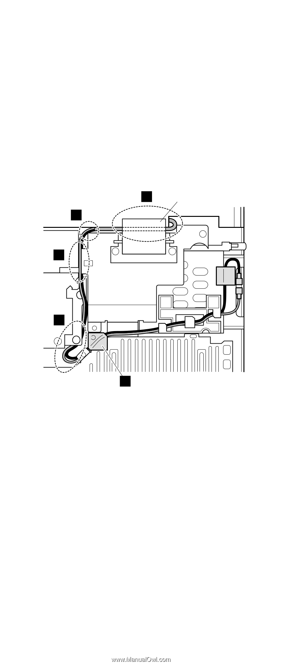
Removing and replacing a FRU 3. Route the cables as follows: a. Route the black cable and the gray cable one through the cable guide. b. Route the cables along the edge of the upper shield and secure them with the insulation tape a . c. Route the cable under LCD flexible cable (A) and alongside the LCD. ( b ) d. Route the cable between the fan assembly and the sub card. ( c ) e. Route the cable between the system board and the stiffener. Only at this point can any extra bend of the cables be allowed. ( d ) b (A) e c d a Note: Make sure that the cable is not on the sub card in e -part in the figure. 104 ThinkPad A22m wireless models
-
 1
1 -
2
-
3
-
4
-
5
-
6
-
7
-
8
-
9
-
10
-
11
-
12
-
13
-
14
-
15
-
16
-
17
-
18
-
19
-
20
-
21
-
22
-
23
-
24
-
25
-
26
-
27
-
28
-
29
-
30
-
31
-
32
-
33
-
34
-
35
-
36
-
37
-
38
-
39
-
40
-
41
-
42
-
43
-
44
-
45
-
46
-
47
-
48
-
49
-
50
-
51
-
52
-
53
-
54
-
55
-
56
-
57
-
58
-
59
-
60
-
61
-
62
-
63
-
64
-
65
-
66
-
67
-
68
-
69
-
70
-
71
-
72
-
73
-
74
-
75
-
76
-
77
-
78
-
79
-
80
-
81
-
82
-
83
-
84
-
85
-
86
-
87
-
88
-
89
-
90
-
91
-
92
-
93
-
94
-
95
-
96
-
97
-
98
-
99
-
100
-
101
-
102
-
 103
103 -
 104
104 -
 105
105 -
 106
106 -
 107
107 -
 108
108 -
 109
109 -
 110
110 -
 111
111 -
 112
112 -
 113
113 -
114
-
115
-
116
-
117
-
118
-
119
-
120
-
121
-
122
-
123
-
124
-
125
-
126
-
127
-
128
-
129
-
130
-
131
-
132
-
133
-
134
-
135
-
136
-
137
-
138
-
139
-
140
 |
 |
3.
Route the cables as follows:
a.
Route the black cable and the gray cable one
through the cable guide.
b.
Route the cables along the edge of the upper
shield and secure them with the insulation tape
±a²
.
c.
Route the cable under LCD flexible cable
(A)
and
alongside the LCD. (
±b²
)
d.
Route the cable between the fan assembly and the
sub card. (
±c²
)
e.
Route the cable between the system board and the
stiffener. Only at this point can any extra bend of
the cables be allowed. (
±d²
)
a
b
c
e
d
(A)
Note:
Make sure that the cable is not on the sub card
in
±e²
-part in the figure.
Removing and replacing a FRU
104
ThinkPad A22m wireless models