Lenovo ThinkPad SL400 Hardware Maintenance Manual - Page 116
route
 |
View all Lenovo ThinkPad SL400 manuals
Add to My Manuals
Save this manual to your list of manuals |
Page 116 highlights
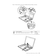
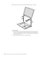
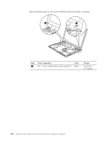
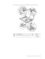
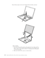
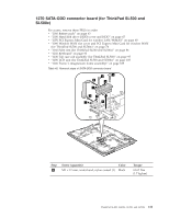
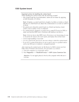
Table 38. Removal steps of LCD unit (for ThinkPad SL500 and SL500c) (continued) 7 8 8 When installing: 1. Route the antenna cables along the cable guides and secure them with the tapes. As you route the cables, make sure that they are not subjected to any tension. Tension could cause the cables to be damaged by the cable guides, or a wire to be broken. 2. Make sure that the LCD connector is attached firmly. 108 ThinkPad SL400, SL400c, SL500, and SL500c Hardware Maintenance Manual
-
 1
1 -
2
-
3
-
4
-
5
-
6
-
7
-
8
-
9
-
10
-
11
-
12
-
13
-
14
-
15
-
16
-
17
-
18
-
19
-
20
-
21
-
22
-
23
-
24
-
25
-
26
-
27
-
28
-
29
-
30
-
31
-
32
-
33
-
34
-
35
-
36
-
37
-
38
-
39
-
40
-
41
-
42
-
43
-
44
-
45
-
46
-
47
-
48
-
49
-
50
-
51
-
52
-
53
-
54
-
55
-
56
-
57
-
58
-
59
-
60
-
61
-
62
-
63
-
64
-
65
-
66
-
67
-
68
-
69
-
70
-
71
-
72
-
73
-
74
-
75
-
76
-
77
-
78
-
79
-
80
-
81
-
82
-
83
-
84
-
85
-
86
-
87
-
88
-
89
-
90
-
91
-
92
-
93
-
94
-
95
-
96
-
97
-
98
-
99
-
100
-
101
-
102
-
103
-
104
-
105
-
106
-
107
-
108
-
109
-
110
-
 111
111 -
 112
112 -
 113
113 -
 114
114 -
 115
115 -
 116
116 -
 117
117 -
 118
118 -
 119
119 -
 120
120 -
 121
121 -
122
-
123
-
124
-
125
-
126
-
127
-
128
-
129
-
130
-
131
-
132
-
133
-
134
-
135
-
136
-
137
-
138
-
139
-
140
-
141
-
142
-
143
-
144
-
145
-
146
-
147
-
148
-
149
-
150
-
151
-
152
-
153
-
154
-
155
-
156
-
157
-
158
-
159
-
160
-
161
-
162
-
163
-
164
-
165
-
166
-
167
-
168
-
169
-
170
-
171
-
172
-
173
-
174
-
175
-
176
-
177
-
178
-
179
-
180
-
181
-
182
-
183
-
184
-
185
-
186
-
187
-
188
-
189
-
190
-
191
-
192
-
193
-
194
-
195
-
196
-
197
-
198
-
199
-
200
-
201
-
202
-
203
-
204
-
205
-
206
-
207
-
208
-
209
-
210
-
211
-
212
-
213
-
214
-
215
-
216
-
217
-
218
-
219
-
220
-
221
-
222
-
223
-
224
-
225
-
226
-
227
-
228
-
229
-
230
-
231
-
232
-
233
-
234
-
235
-
236
-
237
-
238
-
239
-
240
 |
 |
Table
38.
Removal
steps
of
LCD
unit
(for
ThinkPad
SL500
and
SL500c)
(continued)
7
8
8
When
installing:
1.
Route
the
antenna
cables
along
the
cable
guides
and
secure
them
with
the
tapes.
As
you
route
the
cables,
make
sure
that
they
are
not
subjected
to
any
tension.
Tension
could
cause
the
cables
to
be
damaged
by
the
cable
guides,
or
a
wire
to
be
broken.
2.
Make
sure
that
the
LCD
connector
is
attached
firmly.
108
ThinkPad
SL400,
SL400c,
SL500,
and
SL500c
Hardware
Maintenance
Manual