Lenovo ThinkPad SL400 Hardware Maintenance Manual - Page 91
Attention, installing
 |
View all Lenovo ThinkPad SL400 manuals
Add to My Manuals
Save this manual to your list of manuals |
Page 91 highlights
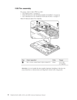
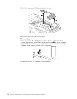
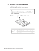
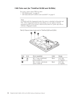
1140 CPU For access, remove these FRUs in order: v "1010 Battery pack" on page 63 v "1100 Thermal door (for ThinkPad SL400 and SL400c)" on page 76 v "1110 Thermal door (for ThinkPad SL500 and SL500c)" on page 77 v "1120 Fan assembly" on page 78 v "1130 CPU thermal module" on page 81 Attention: CPU is extremely sensitive. When you service the CPU, avoid any kind of rough handling. Table 27. Removal steps of CPU Rotate the head of the screw in the direction shown by arrow 1 to release the lock; then remove the CPU. a 1 b 2 When installing: Place the CPU on the CPU socket a , and then rotate the head of the screw in the direction shown by arrow b to secure the CPU. ThinkPad SL400, SL400c, SL500, and SL500c 83
-
 1
1 -
2
-
3
-
4
-
5
-
6
-
7
-
8
-
9
-
10
-
11
-
12
-
13
-
14
-
15
-
16
-
17
-
18
-
19
-
20
-
21
-
22
-
23
-
24
-
25
-
26
-
27
-
28
-
29
-
30
-
31
-
32
-
33
-
34
-
35
-
36
-
37
-
38
-
39
-
40
-
41
-
42
-
43
-
44
-
45
-
46
-
47
-
48
-
49
-
50
-
51
-
52
-
53
-
54
-
55
-
56
-
57
-
58
-
59
-
60
-
61
-
62
-
63
-
64
-
65
-
66
-
67
-
68
-
69
-
70
-
71
-
72
-
73
-
74
-
75
-
76
-
77
-
78
-
79
-
80
-
81
-
82
-
83
-
84
-
85
-
 86
86 -
 87
87 -
 88
88 -
 89
89 -
 90
90 -
 91
91 -
 92
92 -
 93
93 -
 94
94 -
 95
95 -
 96
96 -
97
-
98
-
99
-
100
-
101
-
102
-
103
-
104
-
105
-
106
-
107
-
108
-
109
-
110
-
111
-
112
-
113
-
114
-
115
-
116
-
117
-
118
-
119
-
120
-
121
-
122
-
123
-
124
-
125
-
126
-
127
-
128
-
129
-
130
-
131
-
132
-
133
-
134
-
135
-
136
-
137
-
138
-
139
-
140
-
141
-
142
-
143
-
144
-
145
-
146
-
147
-
148
-
149
-
150
-
151
-
152
-
153
-
154
-
155
-
156
-
157
-
158
-
159
-
160
-
161
-
162
-
163
-
164
-
165
-
166
-
167
-
168
-
169
-
170
-
171
-
172
-
173
-
174
-
175
-
176
-
177
-
178
-
179
-
180
-
181
-
182
-
183
-
184
-
185
-
186
-
187
-
188
-
189
-
190
-
191
-
192
-
193
-
194
-
195
-
196
-
197
-
198
-
199
-
200
-
201
-
202
-
203
-
204
-
205
-
206
-
207
-
208
-
209
-
210
-
211
-
212
-
213
-
214
-
215
-
216
-
217
-
218
-
219
-
220
-
221
-
222
-
223
-
224
-
225
-
226
-
227
-
228
-
229
-
230
-
231
-
232
-
233
-
234
-
235
-
236
-
237
-
238
-
239
-
240
 |
 |

1140
CPU
For
access,
remove
these
FRUs
in
order:
v
“1010
Battery
pack”
on
page
63
v
“1100
Thermal
door
(for
ThinkPad
SL400
and
SL400c)”
on
page
76
v
“1110
Thermal
door
(for
ThinkPad
SL500
and
SL500c)”
on
page
77
v
“1120
Fan
assembly”
on
page
78
v
“1130
CPU
thermal
module”
on
page
81
Attention:
CPU
is
extremely
sensitive.
When
you
service
the
CPU,
avoid
any
kind
of
rough
handling.
Table
27.
Removal
steps
of
CPU
Rotate
the
head
of
the
screw
in
the
direction
shown
by
arrow
±1²
to
release
the
lock;
then
remove
the
CPU.
2
b
1
a
When
installing:
Place
the
CPU
on
the
CPU
socket
±a²
,
and
then
rotate
the
head
of
the
screw
in
the
direction
shown
by
arrow
±b²
to
secure
the
CPU.
ThinkPad
SL400,
SL400c,
SL500,
and
SL500c
83