Lenovo ThinkPad W510 Hardware Maintenance Manual - Page 111
Accelerometer chip for the HDD Active Protection System, MCP Multi Chip Package processor
 |
View all Lenovo ThinkPad W510 manuals
Add to My Manuals
Save this manual to your list of manuals |
Page 111 highlights
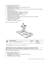
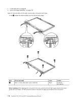
Table 35. Location of major sensitive components on the system board Following components soldered on the top side of the system board are extremely sensitive. When you service the system board, avoid any kind of rough handling. a MCP (Multi Chip Package) processor b PCH (Platform Controller Hub) c Accelerometer chip for the HDD Active Protection System™ d Graphics Note: d (Graphics) is only for the Switchable Graphics models and Workstation models. The system board in Integrated Graphics models does not have this chip. For Integrated Graphics models: a For Switchable Graphics models: a cb d For Workstation models: cb Chapter 9. Removing and replacing a FRU 105
-
 1
1 -
2
-
3
-
4
-
5
-
6
-
7
-
8
-
9
-
10
-
11
-
12
-
13
-
14
-
15
-
16
-
17
-
18
-
19
-
20
-
21
-
22
-
23
-
24
-
25
-
26
-
27
-
28
-
29
-
30
-
31
-
32
-
33
-
34
-
35
-
36
-
37
-
38
-
39
-
40
-
41
-
42
-
43
-
44
-
45
-
46
-
47
-
48
-
49
-
50
-
51
-
52
-
53
-
54
-
55
-
56
-
57
-
58
-
59
-
60
-
61
-
62
-
63
-
64
-
65
-
66
-
67
-
68
-
69
-
70
-
71
-
72
-
73
-
74
-
75
-
76
-
77
-
78
-
79
-
80
-
81
-
82
-
83
-
84
-
85
-
86
-
87
-
88
-
89
-
90
-
91
-
92
-
93
-
94
-
95
-
96
-
97
-
98
-
99
-
100
-
101
-
102
-
103
-
104
-
105
-
 106
106 -
 107
107 -
 108
108 -
 109
109 -
 110
110 -
 111
111 -
 112
112 -
 113
113 -
 114
114 -
 115
115 -
 116
116 -
117
-
118
-
119
-
120
-
121
-
122
-
123
-
124
-
125
-
126
-
127
-
128
-
129
-
130
-
131
-
132
-
133
-
134
-
135
-
136
-
137
-
138
-
139
-
140
-
141
-
142
-
143
-
144
-
145
-
146
-
147
-
148
-
149
-
150
-
151
-
152
-
153
-
154
-
155
-
156
-
157
-
158
-
159
-
160
-
161
-
162
-
163
-
164
-
165
-
166
-
167
-
168
-
169
-
170
-
171
-
172
-
173
-
174
-
175
-
176
-
177
-
178
-
179
-
180
-
181
-
182
-
183
-
184
-
185
-
186
-
187
-
188
-
189
-
190
-
191
-
192
-
193
-
194
-
195
-
196
-
197
-
198
-
199
-
200
-
201
-
202
-
203
-
204
-
205
-
206
-
207
-
208
-
209
-
210
 |
 |
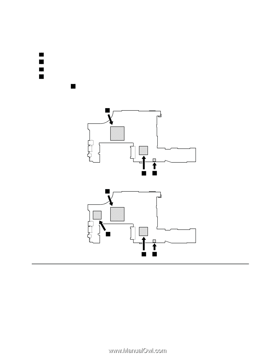
Table 35. Location of major sensitive components on the system board
Following components soldered on the top side of the system board are extremely sensitive. When you service
the system board, avoid any kind of rough handling.
a
MCP (Multi Chip Package) processor
b
PCH (Platform Controller Hub)
c
Accelerometer chip for the HDD Active Protection System
™
d
Graphics
Note:
d
(Graphics) is only for the Switchable Graphics models and Workstation models. The system
board in Integrated Graphics models does not have this chip.
For Integrated Graphics models:
a
b
c
For Switchable Graphics models:
d
a
b
c
For Workstation models:
Chapter 9
.
Removing and replacing a FRU
105