Lenovo ThinkPad W510 Hardware Maintenance Manual - Page 113
LCD bezel assembly, For access, remove this FRU, 1010 Battery pack
 |
View all Lenovo ThinkPad W510 manuals
Add to My Manuals
Save this manual to your list of manuals |
Page 113 highlights
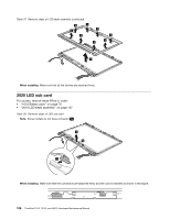
Table 36. Removal steps of system board and magnesium structure frame (continued) When installing: When you replace the system board, attach thermal rubbers as shown in this figure. Depend on the models you are servicing, the number of thermal rubbers are different. Check the thermal rubbers on the old system board, and find duplicates of them in the new FRU package and apply them to the new system board. a b c 2010 LCD bezel assembly For access, remove this FRU: • "1010 Battery pack" on page 70 Table 37. Removal steps of LCD bezel assembly 1 1 1 Step 1 Screw cap Screw (quantity) M2.5 × 6 mm, wafer-head, nylon-coated (3) Color Black Torque 0.392 Nm (4.0 kgfcm) Chapter 9. Removing and replacing a FRU 107
-
 1
1 -
2
-
3
-
4
-
5
-
6
-
7
-
8
-
9
-
10
-
11
-
12
-
13
-
14
-
15
-
16
-
17
-
18
-
19
-
20
-
21
-
22
-
23
-
24
-
25
-
26
-
27
-
28
-
29
-
30
-
31
-
32
-
33
-
34
-
35
-
36
-
37
-
38
-
39
-
40
-
41
-
42
-
43
-
44
-
45
-
46
-
47
-
48
-
49
-
50
-
51
-
52
-
53
-
54
-
55
-
56
-
57
-
58
-
59
-
60
-
61
-
62
-
63
-
64
-
65
-
66
-
67
-
68
-
69
-
70
-
71
-
72
-
73
-
74
-
75
-
76
-
77
-
78
-
79
-
80
-
81
-
82
-
83
-
84
-
85
-
86
-
87
-
88
-
89
-
90
-
91
-
92
-
93
-
94
-
95
-
96
-
97
-
98
-
99
-
100
-
101
-
102
-
103
-
104
-
105
-
106
-
107
-
 108
108 -
 109
109 -
 110
110 -
 111
111 -
 112
112 -
 113
113 -
 114
114 -
 115
115 -
 116
116 -
 117
117 -
 118
118 -
119
-
120
-
121
-
122
-
123
-
124
-
125
-
126
-
127
-
128
-
129
-
130
-
131
-
132
-
133
-
134
-
135
-
136
-
137
-
138
-
139
-
140
-
141
-
142
-
143
-
144
-
145
-
146
-
147
-
148
-
149
-
150
-
151
-
152
-
153
-
154
-
155
-
156
-
157
-
158
-
159
-
160
-
161
-
162
-
163
-
164
-
165
-
166
-
167
-
168
-
169
-
170
-
171
-
172
-
173
-
174
-
175
-
176
-
177
-
178
-
179
-
180
-
181
-
182
-
183
-
184
-
185
-
186
-
187
-
188
-
189
-
190
-
191
-
192
-
193
-
194
-
195
-
196
-
197
-
198
-
199
-
200
-
201
-
202
-
203
-
204
-
205
-
206
-
207
-
208
-
209
-
210
 |
 |
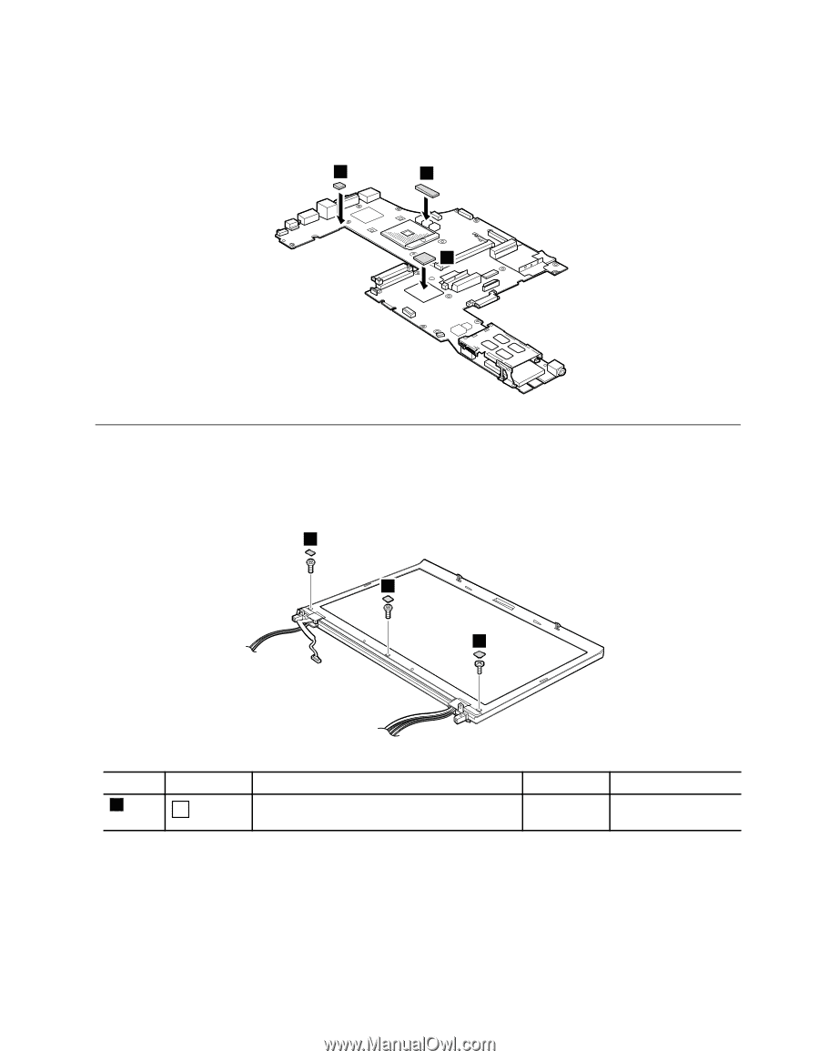
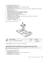
Table 36. Removal steps of system board and magnesium structure frame (continued)
When installing:
When you replace the system board, attach thermal rubbers as shown in this figure. Depend on
the models you are servicing, the number of thermal rubbers are different. Check the thermal rubbers on the old
system board, and find duplicates of them in the new FRU package and apply them to the new system board.
b
c
a
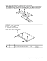
2010 LCD bezel assembly
For access, remove this FRU:
•
“1010 Battery pack” on page 70
Table 37. Removal steps of LCD bezel assembly
1
1
1
Step
Screw cap
Screw (quantity)
Color
Torque
1
M2.5 × 6 mm, wafer-head, nylon-coated (3)
Black
0.392 Nm
(4.0 kgfcm)
Chapter 9
.
Removing and replacing a FRU
107