Lenovo ThinkPad W510 Hardware Maintenance Manual - Page 85
DIMM (upper slot), For access, remove these FRUs in order, 1010 Battery pack
 |
View all Lenovo ThinkPad W510 manuals
Add to My Manuals
Save this manual to your list of manuals |
Page 85 highlights
Table 18. Installation steps of keyboard (continued) 3. Gently press the keys with your thumbs and try to slide the keyboard toward you. 4. Make sure that the front side of the keyboard ( b ) is housed firmly. b b b 5. Secure the keyboard by tightening the screws from the bottom side of the computer. 1070 DIMM (upper slot) For access, remove these FRUs in order: • "1010 Battery pack" on page 70 • "1030 DIMM slot cover" on page 73 • "1060 Keyboard" on page 76 Chapter 9. Removing and replacing a FRU 79
-
 1
1 -
2
-
3
-
4
-
5
-
6
-
7
-
8
-
9
-
10
-
11
-
12
-
13
-
14
-
15
-
16
-
17
-
18
-
19
-
20
-
21
-
22
-
23
-
24
-
25
-
26
-
27
-
28
-
29
-
30
-
31
-
32
-
33
-
34
-
35
-
36
-
37
-
38
-
39
-
40
-
41
-
42
-
43
-
44
-
45
-
46
-
47
-
48
-
49
-
50
-
51
-
52
-
53
-
54
-
55
-
56
-
57
-
58
-
59
-
60
-
61
-
62
-
63
-
64
-
65
-
66
-
67
-
68
-
69
-
70
-
71
-
72
-
73
-
74
-
75
-
76
-
77
-
78
-
79
-
 80
80 -
 81
81 -
 82
82 -
 83
83 -
 84
84 -
 85
85 -
 86
86 -
 87
87 -
 88
88 -
 89
89 -
 90
90 -
91
-
92
-
93
-
94
-
95
-
96
-
97
-
98
-
99
-
100
-
101
-
102
-
103
-
104
-
105
-
106
-
107
-
108
-
109
-
110
-
111
-
112
-
113
-
114
-
115
-
116
-
117
-
118
-
119
-
120
-
121
-
122
-
123
-
124
-
125
-
126
-
127
-
128
-
129
-
130
-
131
-
132
-
133
-
134
-
135
-
136
-
137
-
138
-
139
-
140
-
141
-
142
-
143
-
144
-
145
-
146
-
147
-
148
-
149
-
150
-
151
-
152
-
153
-
154
-
155
-
156
-
157
-
158
-
159
-
160
-
161
-
162
-
163
-
164
-
165
-
166
-
167
-
168
-
169
-
170
-
171
-
172
-
173
-
174
-
175
-
176
-
177
-
178
-
179
-
180
-
181
-
182
-
183
-
184
-
185
-
186
-
187
-
188
-
189
-
190
-
191
-
192
-
193
-
194
-
195
-
196
-
197
-
198
-
199
-
200
-
201
-
202
-
203
-
204
-
205
-
206
-
207
-
208
-
209
-
210
 |
 |
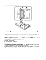
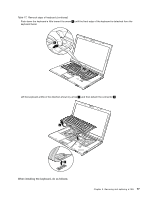
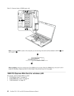
Table 18. Installation steps of keyboard (continued)
3. Gently press the keys with your thumbs and try to slide the keyboard toward you.
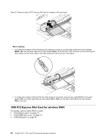
4. Make sure that the front side of the keyboard (
b
) is housed firmly.
b
b
b
5. Secure the keyboard by tightening the screws from the bottom side of the computer.
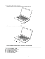
1070 DIMM (upper slot)
For access, remove these FRUs in order:
•
“1010 Battery pack” on page 70
•
“1030 DIMM slot cover” on page 73
•
“1060 Keyboard” on page 76
Chapter 9
.
Removing and replacing a FRU
79