Lenovo ThinkPad X121e Safety and Warranty Guide - ThinkPad X121e - Page 77
LCD unit, 1090 Top case assembly
 |
View all Lenovo ThinkPad X121e manuals
Add to My Manuals
Save this manual to your list of manuals |
Page 77 highlights
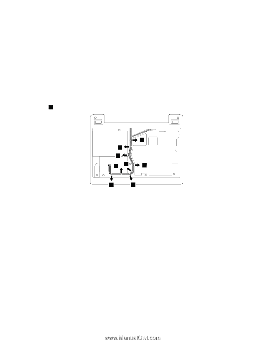
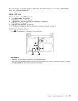
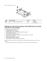
For some models, you need to apply two FCC labels. Check the old base cover; if it has two FCC labels, apply both to the new base cover. 2010 LCD unit For access, remove these FRUs in order: • "1010 Battery pack" on page 50 • "1020 Bottom slot cover" on page 51 • "1040 Hard disk drive or solid state drive assembly" on page 53 • "1070 Keyboard" on page 57 • "1090 Top case assembly" on page 60 • "1130 System board assembly, fan assembly, and backup battery" on page 65 Table 27. Removal steps of LCD unit In step 1 , release the antenna cables from the cable guides. 1 1 1 1 1 1 1 1 When installing: • Make sure that the cables are attached to the cable guides firmly. • When you route the cables, make sure that they are not subjected to any tension. Tension could cause the cables to be damaged by the cable guides, or a wire to be broken. Chapter 8. Removing and replacing a FRU 71
-
 1
1 -
2
-
3
-
4
-
5
-
6
-
7
-
8
-
9
-
10
-
11
-
12
-
13
-
14
-
15
-
16
-
17
-
18
-
19
-
20
-
21
-
22
-
23
-
24
-
25
-
26
-
27
-
28
-
29
-
30
-
31
-
32
-
33
-
34
-
35
-
36
-
37
-
38
-
39
-
40
-
41
-
42
-
43
-
44
-
45
-
46
-
47
-
48
-
49
-
50
-
51
-
52
-
53
-
54
-
55
-
56
-
57
-
58
-
59
-
60
-
61
-
62
-
63
-
64
-
65
-
66
-
67
-
68
-
69
-
70
-
71
-
 72
72 -
 73
73 -
 74
74 -
 75
75 -
 76
76 -
 77
77 -
 78
78 -
 79
79 -
 80
80 -
 81
81 -
 82
82 -
83
-
84
-
85
-
86
-
87
-
88
-
89
-
90
-
91
-
92
-
93
-
94
-
95
-
96
-
97
-
98
-
99
-
100
-
101
-
102
-
103
-
104
-
105
-
106
-
107
-
108
-
109
-
110
-
111
-
112
 |
 |