Lexmark T650DN Service Manual - Page 326
Alignment assembly adjustment, Step
 |
UPC - 734646317344
View all Lexmark T650DN manuals
Add to My Manuals
Save this manual to your list of manuals |
Page 326 highlights
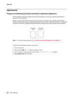
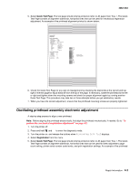
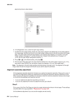
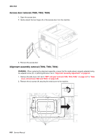
4062-XXX alignment printout is shown below: Lexmark Hd Quick Test Device Information Page Cou nt Installed Memory Processor Speed Serial Number TDS Calibration Engine ID System Card ID 31 192 MB 467MHz 0116413 00 14 FF 00 00 00 00 40 0004007E24A2 Printer Revision Levels Loader Kernel Base Network Netwrk Drvr Engine Panel Font LF.LBH.P055-0 FFN.APS.F191a-0 LF.LBH.P055-0 NF.APS.N179-0 LF.LBH.P055-0 AF.LB.E037-0 9.9 8.31M02-U5.0 Printer Margin Settings Top Margin = 5 Bottom Margin = 0 Left Margin = -3 Right Margin = 0 Dup Top Margin = 0 Dup Left Margin = 0 Paper Source Formatted Size = Tray 1 = Letter - 12 - 10 - 8 - 6 - 4 - 2 0 + 2 + 4 + 6 + 8 + 10 + 12 Darkest bar indicates ADJUSTMENT AMOUNT for bidirectional alignment 6. In the Registration menu, select the right margin setting. 7. To determine the margin setting, choose the value that is closest to the darkest bar on the center graph of the margin page. Add that value to the current right margin setting printed on the left hand side of the margin page. (The right margin setting will also appear on the operator panel display.) For example, if the right margin setting on the page is -2, and the number that is closest to the darkest line on the graph is 3 (-2+3), then the right margin setting will be equal to +1. 8. Press or to the desired setting, and press . 9. Print the Quick Test page again and check that the darkest line in the center graph is equal to zero. If it is, then check to see if the left, top, and bottom margins are detected. If it is not, then repeat step 5. Note: The alignment of the left margin positions the black plane to the right or left. The alignment of the right margin does not alter the margins and should only be used to adjust the printhead. Alignment assembly adjustment Do the alignment assembly adjustment whenever you replace the alignment assembly. Always print a copy of the Quick Test Page before making any adjustments to the alignment assembly reference adjustment screw. When replacing the alignment assembly, it is necessary to back the reference adjustment screw out far enough to remove the old assembly and install the new one. • If you are replacing the alignment assembly, go to step A. • If you are only adjusting the reference adjustment screw, go to step B. Step A Print a copy of the Quick Test Page and check the margin adjustments printed on the test page. These settings should be within the range specified in "Registration" on page 3-67. Do the reference adjustment if you are sure the margins are set correctly. 4-4 Service Manual
-
 1
1 -
2
-
3
-
4
-
5
-
6
-
7
-
8
-
9
-
10
-
11
-
12
-
13
-
14
-
15
-
16
-
17
-
18
-
19
-
20
-
21
-
22
-
23
-
24
-
25
-
26
-
27
-
28
-
29
-
30
-
31
-
32
-
33
-
34
-
35
-
36
-
37
-
38
-
39
-
40
-
41
-
42
-
43
-
44
-
45
-
46
-
47
-
48
-
49
-
50
-
51
-
52
-
53
-
54
-
55
-
56
-
57
-
58
-
59
-
60
-
61
-
62
-
63
-
64
-
65
-
66
-
67
-
68
-
69
-
70
-
71
-
72
-
73
-
74
-
75
-
76
-
77
-
78
-
79
-
80
-
81
-
82
-
83
-
84
-
85
-
86
-
87
-
88
-
89
-
90
-
91
-
92
-
93
-
94
-
95
-
96
-
97
-
98
-
99
-
100
-
101
-
102
-
103
-
104
-
105
-
106
-
107
-
108
-
109
-
110
-
111
-
112
-
113
-
114
-
115
-
116
-
117
-
118
-
119
-
120
-
121
-
122
-
123
-
124
-
125
-
126
-
127
-
128
-
129
-
130
-
131
-
132
-
133
-
134
-
135
-
136
-
137
-
138
-
139
-
140
-
141
-
142
-
143
-
144
-
145
-
146
-
147
-
148
-
149
-
150
-
151
-
152
-
153
-
154
-
155
-
156
-
157
-
158
-
159
-
160
-
161
-
162
-
163
-
164
-
165
-
166
-
167
-
168
-
169
-
170
-
171
-
172
-
173
-
174
-
175
-
176
-
177
-
178
-
179
-
180
-
181
-
182
-
183
-
184
-
185
-
186
-
187
-
188
-
189
-
190
-
191
-
192
-
193
-
194
-
195
-
196
-
197
-
198
-
199
-
200
-
201
-
202
-
203
-
204
-
205
-
206
-
207
-
208
-
209
-
210
-
211
-
212
-
213
-
214
-
215
-
216
-
217
-
218
-
219
-
220
-
221
-
222
-
223
-
224
-
225
-
226
-
227
-
228
-
229
-
230
-
231
-
232
-
233
-
234
-
235
-
236
-
237
-
238
-
239
-
240
-
241
-
242
-
243
-
244
-
245
-
246
-
247
-
248
-
249
-
250
-
251
-
252
-
253
-
254
-
255
-
256
-
257
-
258
-
259
-
260
-
261
-
262
-
263
-
264
-
265
-
266
-
267
-
268
-
269
-
270
-
271
-
272
-
273
-
274
-
275
-
276
-
277
-
278
-
279
-
280
-
281
-
282
-
283
-
284
-
285
-
286
-
287
-
288
-
289
-
290
-
291
-
292
-
293
-
294
-
295
-
296
-
297
-
298
-
299
-
300
-
301
-
302
-
303
-
304
-
305
-
306
-
307
-
308
-
309
-
310
-
311
-
312
-
313
-
314
-
315
-
316
-
317
-
318
-
319
-
320
-
 321
321 -
 322
322 -
 323
323 -
 324
324 -
 325
325 -
 326
326 -
 327
327 -
 328
328 -
 329
329 -
 330
330 -
 331
331 -
332
-
333
-
334
-
335
-
336
-
337
-
338
-
339
-
340
-
341
-
342
-
343
-
344
-
345
-
346
-
347
-
348
-
349
-
350
-
351
-
352
-
353
-
354
-
355
-
356
-
357
-
358
-
359
-
360
-
361
-
362
-
363
-
364
-
365
-
366
-
367
-
368
-
369
-
370
-
371
-
372
-
373
-
374
-
375
-
376
-
377
-
378
-
379
-
380
-
381
-
382
-
383
-
384
-
385
-
386
-
387
-
388
-
389
-
390
-
391
-
392
-
393
-
394
-
395
-
396
-
397
-
398
-
399
-
400
-
401
-
402
-
403
-
404
-
405
-
406
-
407
-
408
-
409
-
410
-
411
-
412
-
413
-
414
-
415
-
416
-
417
-
418
-
419
-
420
-
421
-
422
-
423
-
424
-
425
-
426
-
427
-
428
-
429
-
430
-
431
-
432
-
433
-
434
-
435
-
436
-
437
-
438
-
439
-
440
-
441
-
442
-
443
-
444
-
445
-
446
-
447
-
448
-
449
-
450
-
451
-
452
-
453
-
454
-
455
-
456
-
457
-
458
-
459
-
460
-
461
-
462
-
463
-
464
-
465
-
466
-
467
-
468
-
469
-
470
-
471
-
472
-
473
-
474
-
475
-
476
-
477
-
478
-
479
-
480
-
481
-
482
-
483
-
484
-
485
-
486
-
487
-
488
-
489
-
490
-
491
-
492
-
493
-
494
-
495
-
496
-
497
-
498
-
499
-
500
-
501
-
502
-
503
-
504
-
505
-
506
-
507
-
508
-
509
-
510
-
511
-
512
-
513
-
514
-
515
-
516
-
517
-
518
-
519
-
520
-
521
-
522
-
523
-
524
-
525
-
526
-
527
-
528
-
529
-
530
-
531
-
532
-
533
-
534
-
535
-
536
-
537
-
538
-
539
-
540
-
541
-
542
-
543
-
544
-
545
-
546
-
547
-
548
-
549
-
550
-
551
-
552
-
553
-
554
-
555
-
556
-
557
-
558
-
559
-
560
-
561
-
562
-
563
-
564
-
565
-
566
-
567
-
568
-
569
-
570
-
571
-
572
-
573
-
574
-
575
-
576
-
577
-
578
-
579
-
580
-
581
-
582
-
583
-
584
-
585
-
586
-
587
-
588
 |
 |
