Lexmark X264dn Service Manual - Page 78
Tray 2 service check, ADF Disabled
 |
UPC - 734646140584
View all Lexmark X264dn manuals
Add to My Manuals
Save this manual to your list of manuals |
Page 78 highlights
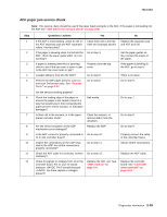
7013-XXX Tray 2 service check FRU Tray 2 Action Turn the printer off. Separate the printer from Tray 2. Turn the printer on and check the voltages on connector J28 on the controller board. See the wiring diagram at the end of the service manual, or "Controller board connector pin values" on page 5-3 for the J31 connector. Pins 1, 4: 3.3 V Pin 2: 24 V Pin 6: Ground If the voltages are incorrent, then replace the controller board. If the voltages are correct, then try using Tray 2 again. If the printer error persists, then replace Tray 2. 840.xx service check Step 1 2 3 4 5 Questions / actions Yes POR the machine into configuration mode. Go to the disable scanner menu item. See "Disable Scanner" on page 3-31. Select "Enable ADF/FB -Enabled and press to save the change. POR the MFP to operating mode. Try running a copy from the ADF and flatbed. Go to step 2. Did the 840.xx error recur? Re-enter Configuration mode, scroll to and select the Disable Scanner menu item. Does the screen display ADF Disabled or Auto Disabled? Check the ADF cable connections on the ADF relay card and connector J4 on the controller board. Also inspect the cable connections on JFBM1, J1 and J2 on the controller board. Go to step 3. Go to step 5. Are the connections properly connected? Properly connect the connections on the ADF relay card and controller board. POR the machine into configuration mode. Go to the disable scanner menu item. See "Disable Scanner" on page 3-31. Select "Enable ADF/FB -Enabled and press to save the change. POR the MFP to operating mode. Try running a copy from the ADF and flatbed. Go to step 5. Did the 840.xx error recur? Check the continuity on the ADF cable. Go to step 7. Is there continuity? No Stop. Problem resolved. Go to step 8. Go to step 4. Stop. Problem solved. Go to step 6. 2-44 Service Manual
-
 1
1 -
2
-
3
-
4
-
5
-
6
-
7
-
8
-
9
-
10
-
11
-
12
-
13
-
14
-
15
-
16
-
17
-
18
-
19
-
20
-
21
-
22
-
23
-
24
-
25
-
26
-
27
-
28
-
29
-
30
-
31
-
32
-
33
-
34
-
35
-
36
-
37
-
38
-
39
-
40
-
41
-
42
-
43
-
44
-
45
-
46
-
47
-
48
-
49
-
50
-
51
-
52
-
53
-
54
-
55
-
56
-
57
-
58
-
59
-
60
-
61
-
62
-
63
-
64
-
65
-
66
-
67
-
68
-
69
-
70
-
71
-
72
-
 73
73 -
 74
74 -
 75
75 -
 76
76 -
 77
77 -
 78
78 -
 79
79 -
 80
80 -
 81
81 -
 82
82 -
 83
83 -
84
-
85
-
86
-
87
-
88
-
89
-
90
-
91
-
92
-
93
-
94
-
95
-
96
-
97
-
98
-
99
-
100
-
101
-
102
-
103
-
104
-
105
-
106
-
107
-
108
-
109
-
110
-
111
-
112
-
113
-
114
-
115
-
116
-
117
-
118
-
119
-
120
-
121
-
122
-
123
-
124
-
125
-
126
-
127
-
128
-
129
-
130
-
131
-
132
-
133
-
134
-
135
-
136
-
137
-
138
-
139
-
140
-
141
-
142
-
143
-
144
-
145
-
146
-
147
-
148
-
149
-
150
-
151
-
152
-
153
-
154
-
155
-
156
-
157
-
158
-
159
-
160
-
161
-
162
-
163
-
164
-
165
-
166
-
167
-
168
-
169
-
170
-
171
-
172
-
173
-
174
-
175
-
176
-
177
-
178
-
179
-
180
-
181
-
182
-
183
-
184
-
185
-
186
-
187
-
188
-
189
-
190
-
191
-
192
-
193
-
194
-
195
-
196
-
197
-
198
-
199
-
200
-
201
-
202
-
203
-
204
-
205
-
206
-
207
-
208
-
209
-
210
-
211
-
212
-
213
-
214
-
215
-
216
-
217
-
218
-
219
-
220
-
221
-
222
-
223
-
224
-
225
-
226
-
227
-
228
-
229
-
230
-
231
-
232
-
233
-
234
-
235
-
236
-
237
-
238
-
239
-
240
-
241
-
242
-
243
-
244
-
245
-
246
-
247
-
248
-
249
-
250
 |
 |
