LiftMaster 8550 8550 Manual - Page 19
Install the Safety Reversing Sensors, Wire the Safety Reversing, Sensors
 |
View all LiftMaster 8550 manuals
Add to My Manuals
Save this manual to your list of manuals |
Page 19 highlights
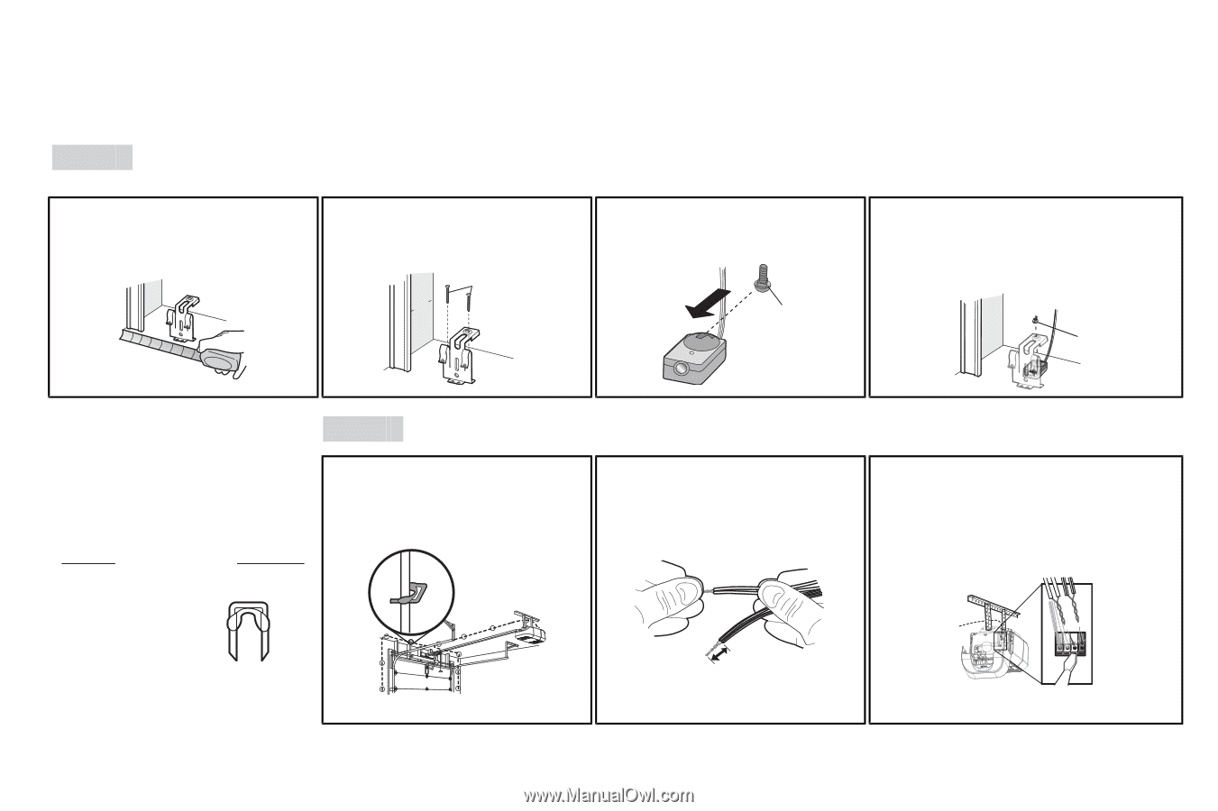
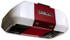
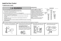
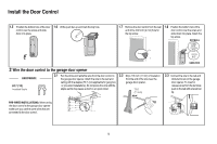
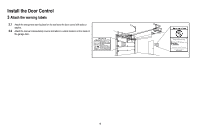
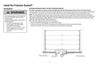
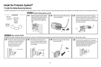
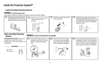
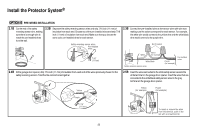
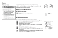
Install the Protector System® 1 Install the Safety Reversing Sensors OPTION C FLOOR INSTALLATION Use an extension bracket (not provided) or wood black to raise the sensor bracket if needed. 1.1C Carefully measure the position of both sensor brackets so they will be the same distance from the wall and unobstructed. 1.2C Attach the sensor brackets to the floor using concrete anchors (not provided). (not provided) IGWnsaairdlalege 1.3C Slide the carriage bolt (H12) into the slot on each sensor. H12 1.4C Insert the bolt through the hole in the sensor bracket and attach with the wing nut (H13). The lens on both sensors should point toward each other. Make sure the lens is not obstructed by the sensor bracket. H13 2 Wire the Safety Reversing Sensors OPTION A INSTALLATION WITHOUT PRE-WIRING PRE-WIRED INSTALLATIONS: If your garage already has wires installed for the safety reversing sensors, refer to the instructions on the following page. 2.1A Run the wire from both sensors to the garage door opener. Attach the wire to the wall and ceiling with the staples (H17). 2.2A Strip 7/16 inch (11 mm) of insulation from each set of wires. Separate the wires. Twist the white wires together. Twist the white/black wires together. HARDWARE H17 H17 (10) Insulated Staple 7/16" (11 mm) 2.3A Insert the white wires into the white terminal on the garage door opener. Insert the white/black wires into the grey terminal on the garage door opener. To insert or remove the wires from the terminal, push in the tab with a screwdriver tip. RED WHITE WHITE GREY 19
-
 1
1 -
2
-
3
-
4
-
5
-
6
-
7
-
8
-
9
-
10
-
11
-
12
-
13
-
 14
14 -
 15
15 -
 16
16 -
 17
17 -
 18
18 -
 19
19 -
 20
20 -
 21
21 -
 22
22 -
 23
23 -
 24
24 -
25
-
26
-
27
-
28
-
29
-
30
-
31
-
32
-
33
-
34
-
35
-
36
-
37
-
38
-
39
-
40
 |
 |