LiftMaster GH GH LOGIC VERSION 2 Manual - Page 12
Logic Control Ver. 2.0 3 Phase Wiring Diagram
 |
View all LiftMaster GH manuals
Add to My Manuals
Save this manual to your list of manuals |
Page 12 highlights
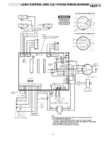
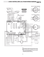
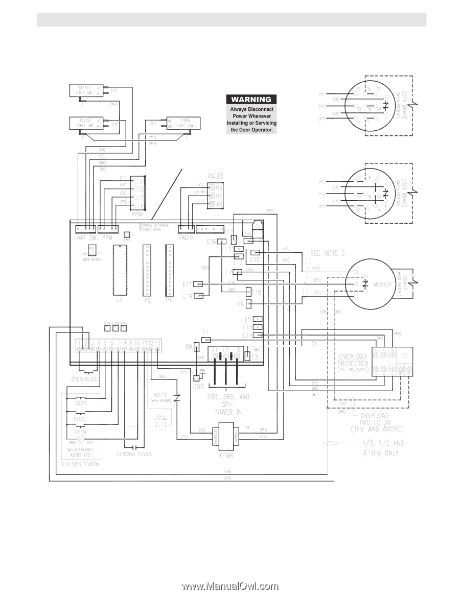
LOGIC CONTROL (VER. 2.0) 3 PHASE WIRING DIAGRAM 1837-3 380/460 VOLT MOTOR CONNECTION NOTE: Contactor 1 PH / 3 PH jumper should be in 3 PH position. 230 VOLT MOTOR CONNECTION Notes: 1) See Ownerʼs Manual for Dip Switch Functions and Programming Procedures 2) TO REVERSE MOTOR DIRECTION: INTERCHANGE ANY 2 OF THE 3 POWER WIRES AT L1, L2 & L3, OR EXCHANGE PURPLE & GRAY MOTOR LEADS AT BOARD CONNECTIONS E17 & E6 (3PH UNITS ONLY). **- Transformer Primary Voltage same as Line Voltage. 12
-
 1
1 -
2
-
3
-
4
-
5
-
6
-
 7
7 -
 8
8 -
 9
9 -
 10
10 -
 11
11 -
 12
12 -
 13
13 -
 14
14 -
 15
15 -
 16
16 -
 17
17 -
18
-
19
-
20
-
21
-
22
-
23
-
24
-
25
-
26
-
27
-
28
 |
 |
12
LOGIC CONTROL (VER. 2.0) 3 PHASE WIRING DIAGRAM
1
8
37-3
230 VOLT MOTOR CONNECTION
380/460 VOLT MOTOR CONNECTION
Notes:
1)
See Ownerʼs Manual for Dip Switch Functions and Programming Procedures
2)
TO REVERSE MOTOR DIRECTION:
INTERCHANGE ANY 2 OF THE 3 POWER
WIRES
AT L1, L2 & L3, OR EXCHANGE PURPLE & GRAYMOTOR LEADS AT BOARD
CONNECTIONS E17 & E6 (3PH UNITS ONLY).
**- Transformer Primary Voltage same as Line Voltage.
NOTE:
Contactor 1 PH / 3 PH jumper
should be in 3 PH position.