LiftMaster GH GH LOGIC VERSION 2 Manual - Page 2

Table Of Contents, Packing List - 50

Page 2 highlights

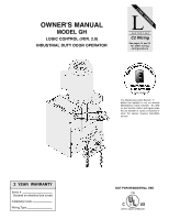
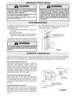
Before attempting to install, operate or maintain the operator, you must read and fully understand this manual and follow all safety instructions. These instructions are intended to highlight certain safety related issues. These instructions are not intended to be comprehensive. Because each application is unique, it is the responsibility of the purchaser, designer, installer and end user to ensure that the total door system is safe for its intended use. TABLE OF CONTENTS SPECIFICATIONS Packing List 2 Motor Specification 3 Electrical Specifications 3 Mechanical Specifications 3 Safety Specifications 3 Weights & Dimensions 3 PREPARATION Site 4 Operator 4 INSTALLATION INSTRUCTIONS Wall Mounting 5 Bracket or Shelf Mounting 5 Hand Chain 6 Chain Keeper/Keyhold Bracket 6 ENTRAPMENT PROTECTION ACCESSORIES Emergency Manual Operation 6 Contact Reversing Edge Device 6 Sensing Edges & Photo Eyes 7 LIMIT SWITCH ADJUSTMENT Limit Location 7 Adjustment 7 POWER & CONTROL WIRING Safety Warnings 8 Power Wiring 9 Ground Wiring 9 Control Station Wiring 9 Radio Controls 9 Mounting Instructions 9 Optional Control Mounting 9 Optional Control Wiring 28 CLUTCH ADJUSTMENT Clutch Parts 10 Clutch Adjustment 10 BRAKE ADJUSTMENT Brake Parts 10 WIRING DIAGRAMS 1 PH Wiring 11 3 PH Wiring 12 1 PH Wiring w/Contactor 13 STANDARD PROGRAMMING Wiring Type 14 & 15 RPM Sensor 16 Maximum Run Timer 16 Maintenance Alert System 17 OPTIONAL PROGRAMMING Mid Stop 17 Timer to Close 18 Red Green Warning Lights 18 Board Illustration 19 REPLACEMENT PARTS & MAINTENANCE Trouble Shooting Guide 20 & 21 Maintenance Schedule 22 Customer Service Contact Information 22 Electrical Box parts 23 & 24 Chassis Parts (J 25 & 26 PACKING LIST Before beginning your installation check that all components were supplied and received undamaged. PACKING LIST K77-14334 PART # 14-10896 19-10929-29 77-11090 19-50106M 02-103L DESCRIPTION GH PARTS BOX 29 FT HAND CHAIN GH PARTS BAG # 50 CHAIN, 106 PITCH 3 BUTTON CONTROL STATION QTY 1 1 1 1 1 2

  • 1
  • 2
  • 3
  • 4
  • 5
  • 6
  • 7
  • 8
  • 9
  • 10
  • 11
  • 12
  • 13
  • 14
  • 15
  • 16
  • 17
  • 18
  • 19
  • 20
  • 21
  • 22
  • 23
  • 24
  • 25
  • 26
  • 27
  • 28

TABLE OF CONTENTS
SPECIFICA
TIONS
Packing List . . . . . . . . . . . . . . . . . . . . . . . . . . . . . . . .2
Motor Specification . . . . . . . . . . . . . . . . . . . . . . . . . .3
Electrical Specifications
. . . . . . . . . . . . . . . . . . . . . .3
Mechanical Specifications . . . . . . . . . . . . . . . . . . . . .3
Safety Specifications . . . . . . . . . . . . . . . . . . . . . . . . .3
Weights & Dimensions . . . . . . . . . . . . . . . . . . . . . . .3
PREP
ARA
TION
Site . . . . . . . . . . . . . . . . . . . . . . . . . . . . . . . . . . . . . . . . . .4
Operator . . . . . . . . . . . . . . . . . . . . . . . . . . . . . . . . . . . . . .4
INST
ALLA
TION INSTRUCTIONS
Wall Mounting . . . . . . . . . . . . . . . . . . . . . . . . . . . . . . . . .5
Bracket or Shelf Mounting
. . . . . . . . . . . . . . . . . . . . . . .5
Hand Chain . . . . . . . . . . . . . . . . . . . . . . . . . . . . . . . . . . .6
Chain Keeper/Keyhold Bracket
. . . . . . . . . . . . . . . . . . .6
ENTRAPMENT PROTECTION
ACCESSORIES
Emergency Manual Operation . . . . . . . . . . . . . . . . . . . .6
Contact Reversing Edge Device
. . . . . . . . . . . . . . . . . .6
Sensing Edges & Photo Eyes
. . . . . . . . . . . . . . . . . . . .7
LIMIT SWITCH
ADJUSTMENT
Limit Location
. . . . . . . . . . . . . . . . . . . . . . . . . . . . . . . . .7
Adjustment . . . . . . . . . . . . . . . . . . . . . . . . . . . . . . . . . . . .7
POWER & CONTROL
WIRING
Safety Warnings
. . . . . . . . . . . . . . . . . . . . . . . . . . . . . . .8
Power Wiring . . . . . . . . . . . . . . . . . . . . . . . . . . . . . . . . . .9
Ground Wiring . . . . . . . . . . . . . . . . . . . . . . . . . . . . . .9
Control Station Wiring . . . . . . . . . . . . . . . . . . . . . . . .9
Radio Controls
. . . . . . . . . . . . . . . . . . . . . . . . . . . . .9
Mounting Instructions . . . . . . . . . . . . . . . . . . . . . . . .9
Optional Control Mounting
. . . . . . . . . . . . . . . . . . . .9
Optional Control Wiring . . . . . . . . . . . . . . . . . . . . . . .28
CLUTCH
ADJUSTMENT
Clutch Parts
. . . . . . . . . . . . . . . . . . . . . . . . . . . . . . .10
Clutch Adjustment . . . . . . . . . . . . . . . . . . . . . . . . . . .10
BRAKE
ADJUSTMENT
Brake Parts . . . . . . . . . . . . . . . . . . . . . . . . . . . . . . . .10
WIRING DIAGRAMS
1 PH Wiring . . . . . . . . . . . . . . . . . . . . . . . . . . . . . . . .11
3 PH Wiring . . . . . . . . . . . . . . . . . . . . . . . . . . . . . . . .12
1 PH Wiring w/Contactor
. . . . . . . . . . . . . . . . . . . . .13
ST
ANDARD PROGRAMMING
Wiring Type . . . . . . . . . . . . . . . . . . . . . . . . . . . . . . . .14 & 15
RPM Sensor . . . . . . . . . . . . . . . . . . . . . . . . . . . . . . .16
Maximum Run Timer . . . . . . . . . . . . . . . . . . . . . . . . .16
Maintenance Alert System
. . . . . . . . . . . . . . . . . . . .17
OPTIONAL
PROGRAMMING
Mid Stop . . . . . . . . . . . . . . . . . . . . . . . . . . . . . . . . . .17
Timer to Close . . . . . . . . . . . . . . . . . . . . . . . . . . . . . .18
Red Green Warning Lights . . . . . . . . . . . . . . . . . . . .18
Board Illustration . . . . . . . . . . . . . . . . . . . . . . . . . . . .19
REPLACEMENT P
ARTS & MAINTENANCE
Trouble Shooting Guide
. . . . . . . . . . . . . . . . . . . . . .20 & 21
Maintenance Schedule . . . . . . . . . . . . . . . . . . . . . . .22
Customer Service Contact Information . . . . . . . . . . .22
Electrical Box parts . . . . . . . . . . . . . . . . . . . . . . . . . .23 & 24
Chassis Parts
(J) . . . . . . . . . . . . . . . . . . . . . . . . . . .25 & 26
PACKING LIST
Before beginning your installation check that all components were supplied and received undamaged.
Before attempting to install, operate or maintain the operator, you must read and fully under-
stand this manual and follow all safety instructions.
These instructions are intended to highlight certain safety related issues.
These instruc-
tions are not intended to be comprehensive. Because each application is unique, it is the
responsibility of the purchaser, designer, installer and end user to ensure that the total
door system is safe for its intended use.
2
DESCRIPTION
GH PARTS BOX
29 FT HAND CHAIN
GH PARTS BAG
# 50 CHAIN, 106 PITCH
3 BUTTON CONTROL STATION
P
ART #
14-10896
19-10929-29
77-11090
19-50106M
02-103L
QTY
1
1
1
1
1
PACKING LIST K77-14334