LiftMaster HCTDCU HCTDCU Installation Manual - Page 2

Table Of Contents, Safety, Safety Symbol And Signal Word Review, Usage Class - manual

Page 2 highlights

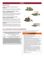
TABLE OF CONTENTS SAFETY 2 SAFETY SYMBOL AND SIGNAL WORD REVIEW 2 USAGE CLASS 3 UL325 ENTRAPMENT PROTECTION REQUIREMENTS 3 SAFETY INSTALLATION INFORMATION 4 GATE CONSTRUCTION INFORMATION 5 INTRODUCTION 6 CARTON INVENTORY 6 OPERATOR SPECIFICATIONS 7 OVERVIEW OF TYPICAL INSTALLATION 8 INSTALLATION 9 IMPORTANT SAFETY INFORMATION 9 CONNECT RAIL TO OPERATOR 10 INSTALL VENTED PLUG 11 DETERMINE LOCATION FOR OPERATOR 11 MOUNT THE OPERATOR 12 INSTALL ENTRAPMENT PROTECTION 13 WIRING 15 POWER WIRING 15 CONNECT BATTERIES AND ATTACH ANTENNA 16 ADJUSTMENT 17 LIMIT AND FORCE ADJUSTMENT 17 OBSTRUCTION TEST 18 OPERATOR OVERVIEW 19 PROGRAMMING 20 REMOTE CONTROLS (NOT PROVIDED 20 LIFTMASTER INTERNET GATEWAY (NOT PROVIDED 21 ERASE ALL CODES 21 ERASE LIMITS 21 TO REMOVE AND ERASE MONITORED ENTRAPMENT PROTECTION DEVICES 21 LIMIT SETUP WITH A REMOTE CONTROL 22 OPERATION 23 GATE/DOOR OPERATOR SETUP EXAMPLES 23 CONTROL BOARD OVERVIEW 24 RESET BUTTON 25 OPERATOR ALARM 25 ADJUSTABLE OPEN SPEED 25 REMOTE CONTROL 25 MANUAL DISCONNECT 26 ACCESSORY WIRING 27 EXTERNAL CONTROL DEVICES 27 EXTERNAL RESET BUTTON 27 MISCELLANEOUS WIRING 28 EXPANSION BOARD 30 EXPANSION BOARD OVERVIEW 30 AUXILIARY RELAYS 31 WIRING ACCESSORIES TO THE EXPANSION BOARD 32 MAINTENANCE 33 IMPORTANT SAFETY INFORMATION 33 MAINTENANCE CHART 33 BATTERIES 33 TROUBLESHOOTING 34 DIAGNOSTIC CODES 34 CONTROL BOARD LEDS 37 TROUBLESHOOTING CHART 38 WIRING DIAGRAM 41 REPAIR PARTS 42 ACCESSORIES 43 WARRANTY 45 SAFETY SAFETY SYMBOL AND SIGNAL WORD REVIEW When you see these Safety Symbols and Signal Words on the following pages, they will alert you to the possibility of Serious Injury or Death if you do not comply with the warnings that accompany them. The hazard may come from something mechanical or from electric shock. Read the warnings carefully. When you see this Signal Word on the following pages, it will alert you to the possibility of damage to your gate/door and/or the gate/door operator if you do not comply with the cautionary statements that accompany it. Read them carefully. IMPORTANT NOTE: • BEFORE attempting to install, operate or maintain the operator, you must read and fully understand this manual and follow all safety instructions. • Operator intended to be installed on a properly balanced gate/door only. Make sure gate/door is properly balanced before installing. • DO NOT attempt repair or service of your operator unless you are an Authorized Service Technician. 2 MECHANICAL ELECTRICAL

  • 1
  • 2
  • 3
  • 4
  • 5
  • 6
  • 7
  • 8
  • 9
  • 10
  • 11
  • 12
  • 13
  • 14
  • 15
  • 16
  • 17
  • 18
  • 19
  • 20
  • 21
  • 22
  • 23
  • 24
  • 25
  • 26
  • 27
  • 28
  • 29
  • 30
  • 31
  • 32
  • 33
  • 34
  • 35
  • 36
  • 37
  • 38
  • 39
  • 40
  • 41
  • 42
  • 43
  • 44
  • 45
  • 46
  • 47
  • 48
  • 49
  • 50
  • 51
  • 52
  • 53
  • 54
  • 55
  • 56
  • 57
  • 58
  • 59
  • 60
  • 61
  • 62
  • 63
  • 64
  • 65
  • 66
  • 67
  • 68
  • 69
  • 70
  • 71
  • 72
  • 73
  • 74
  • 75
  • 76
  • 77
  • 78
  • 79
  • 80
  • 81
  • 82
  • 83
  • 84
  • 85
  • 86
  • 87
  • 88
  • 89
  • 90
  • 91
  • 92

2
SAFETY
SAFETY SYMBOL AND SIGNAL WORD REVIEW
When you see these Safety Symbols and Signal Words on the following pages,
they will alert you to the possibility of
Serious Injury or Death
if you do not
comply with the warnings that accompany them. The hazard may come from
something mechanical or from electric shock. Read the warnings carefully.
When you see this Signal Word on the following pages, it will alert you to the
possibility of damage to your gate/door and/or the gate/door operator if you do
not comply with the cautionary statements that accompany it. Read them
carefully.
IMPORTANT NOTE:
BEFORE attempting to install, operate or maintain the operator, you must
read and fully understand this manual and follow all safety instructions.
Operator intended to be installed on a properly balanced gate/door only. Make
sure gate/door is properly balanced before installing.
DO NOT attempt repair or service of your operator unless you are an
Authorized Service Technician.
TABLE OF CONTENTS
SAFETY
2
SAFETY SYMBOL AND SIGNAL WORD REVIEW
..................................
2
USAGE CLASS
.......................................................................................
3
UL325 ENTRAPMENT PROTECTION REQUIREMENTS
..........................
3
SAFETY INSTALLATION INFORMATION
................................................
4
GATE CONSTRUCTION INFORMATION
..................................................
5
INTRODUCTION
6
CARTON INVENTORY
............................................................................
6
OPERATOR SPECIFICATIONS
................................................................
7
OVERVIEW OF TYPICAL INSTALLATION
...............................................
8
INSTALLATION
9
IMPORTANT SAFETY INFORMATION
....................................................
9
CONNECT RAIL TO OPERATOR
...........................................................
10
INSTALL VENTED PLUG
......................................................................
11
DETERMINE LOCATION FOR OPERATOR
............................................
11
MOUNT THE OPERATOR
.....................................................................
12
INSTALL ENTRAPMENT PROTECTION
................................................
13
WIRING
15
POWER WIRING
..................................................................................
15
CONNECT BATTERIES AND ATTACH ANTENNA
..................................
16
ADJUSTMENT
17
LIMIT AND FORCE ADJUSTMENT
.......................................................
17
OBSTRUCTION TEST
...........................................................................
18
OPERATOR OVERVIEW
19
PROGRAMMING
20
REMOTE CONTROLS (NOT PROVIDED)
..............................................
20
LIFTMASTER INTERNET GATEWAY (NOT PROVIDED)
.......................
21
ERASE ALL CODES
..............................................................................
21
ERASE LIMITS
.....................................................................................
21
TO REMOVE AND ERASE MONITORED ENTRAPMENT
PROTECTION DEVICES
........................................................................
21
LIMIT SETUP WITH A REMOTE CONTROL
..........................................
22
OPERATION
23
GATE/DOOR OPERATOR SETUP EXAMPLES
.......................................
23
CONTROL BOARD OVERVIEW
.............................................................
24
RESET BUTTON
...................................................................................
25
OPERATOR ALARM
.............................................................................
25
ADJUSTABLE OPEN SPEED
.................................................................
25
REMOTE CONTROL
.............................................................................
25
MANUAL DISCONNECT
.......................................................................
26
ACCESSORY WIRING
27
EXTERNAL CONTROL DEVICES
...........................................................
27
EXTERNAL RESET BUTTON
.................................................................
27
MISCELLANEOUS WIRING
..................................................................
28
EXPANSION BOARD
30
EXPANSION BOARD OVERVIEW
.........................................................
30
AUXILIARY RELAYS
............................................................................
31
WIRING ACCESSORIES TO THE EXPANSION BOARD
.........................
32
MAINTENANCE
33
IMPORTANT SAFETY INFORMATION
..................................................
33
MAINTENANCE CHART
........................................................................
33
BATTERIES
..........................................................................................
33
TROUBLESHOOTING
34
DIAGNOSTIC CODES
...........................................................................
34
CONTROL BOARD LEDS
......................................................................
37
TROUBLESHOOTING CHART
...............................................................
38
WIRING DIAGRAM
41
REPAIR PARTS
42
ACCESSORIES
43
WARRANTY
45
MECHANICAL
ELECTRICAL