LiftMaster HCTDCU HCTDCU Installation Manual - Page 5
Gate Construction Information, General Requirements, Specific Applications
 |
View all LiftMaster HCTDCU manuals
Add to My Manuals
Save this manual to your list of manuals |
Page 5 highlights
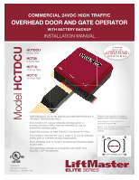
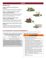
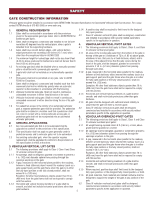
SAFETY GATE CONSTRUCTION INFORMATION Vehicular gates should be installed in accordance with ASTM F2200: Standard Specification for Automated Vehicular Gate Construction. For a copy, contact ASTM directly at 610-832-9585 or www.astm.org. 1. GENERAL REQUIREMENTS 3.1.4 1.1 Gates shall be constructed in accordance with the provisions given for the appropriate gate type listed, refer to ASTM F2200 for 3.2 additional gate types. 1.2 Gates shall be designed, constructed and installed to not fall over more than 45 degrees from the vertical plane, when a gate is 4. detached from the supporting hardware. 4.1 1.3 Gates shall have smooth bottom edges, with vertical bottom edged protrusions not exceeding 0.50 inches (12.7 mm) when other than the exceptions listed in ASTM F2200. 4.1.1 1.4 The minimum height for barbed tape shall not be less than 8 feet (2.44 m) above grade and for barbed wire shall not be less than 6 feet (1.83 m) above grade. 1.5 An existing gate latch shall be disabled when a manually operated gate is retrofitted with a powered gate operator. 1.6 A gate latch shall not be installed on an automatically operated 4.1.2 gate. 1.7 Protrusions shall not be permitted on any gate, refer to ASTM F2200 for Exceptions. 1.8 Gates shall be designed, constructed and installed such that their movement shall not be initiated by gravity when an automatic operator is disconnected, in accordance with the following. 1.8.1 Vehicular horizontal slide gate. Shall not result in continuous, unimpeded movement in either lineal direction of its travel. 4.1.3 1.8.2 Vehicular horizontal swing gate. Shall not result in continuous, unimpeded movement in either direction along the arc of its path of travel. 4.1.4 1.9 For pedestrian access in the vicinity of an automated vehicular gate, a separate pedestrian gate shall be provided. The pedestrian 4.2 gate shall be installed in a location such that a pedestrian shall not come in contact with a moving vehicular access gate. A pedestrian gate shall not be incorporated into an automated 5. vehicular gate panel. 5.1 2. SPECIFIC APPLICATIONS 2.1 Any non-automated gate that is to be automated shall be upgraded to conform to the provisions of this specification. 2.2 This specification shall not apply to gates generally used for pedestrian access and to vehicular gates not to be automated. 2.3 Any existing automated gate, when the operator requires replacement, shall be upgraded to conform to the provisions of this specification in effect at that time. 5.1.1 5.1.2 5.1.3 3. VEHICULAR VERTICAL LIFT GATES 3.1 3.1.1 3.1.2 3.1.3 The following provisions shall apply to Class I, Class II and Class III vehicular vertical lift gates: All openings shall be designed, guarded or screened to prevent a 4 in. (102 mm) diameter sphere from passing through the openings anywhere in the gate. A gap, measured in the horizontal plane parallel to the roadway, between a fixed stationary object nearest the roadway (such as a gate support post) and the gate frame when the gate is in either the fully open position or the fully closed position, shall not exceed 4 in. (102 mm). Exception: All other fixed stationary objects greater than 16 in. (406 mm) from the gate frame shall not be required to comply with this section. Horizontal and vertical framing members of a gate shall be smooth, and shall not include horizontal protrusions other than gate hardware. 5.1.4 5.1.5 5.1.6 5.2 5 A positive stop shall be required to limit travel to the designed fully open position. Class IV vehicular vertical lift gates shall be designed, constructed and installed in accordance with security related parameters specific to the application in question. VEHICULAR VERTICAL PIVOT GATES The following provisions shall apply to Class I, Class II, and Class III vehicular vertical pivot gates: All areas of the moving gate panel from the bottom of the gate to the top of the gate or a minimum of 72 in. (1.83 m) above grade, whichever is less, that pass by a fixed stationary object, and in the area of the adjacent fence that the gate covers during the travel of the gate, shall be designed, guarded or screened to prevent a 2 1⁄4 in. (57 mm) diameter sphere from passing through such areas. A gap, measured in the horizontal plane parallel to the roadway, between a fixed stationary object nearest the roadway (such as a gate support post) and the gate frame when the gate is in either the fully open position or the fully closed position, shall not exceed 4 in. (102 mm). Exception: All other fixed stationary objects greater than 16 in. (406 mm) from the gate frame shall not be required to comply with this section. Horizontal and vertical framing members of a gate shall be smooth, and shall not include protrusions other than gate hardware. All gates shall be designed with sufficient lateral stability to assure that the gate will enter a receiver guide. Class IV vehicular vertical pivot gates shall be designed, constructed and installed in accordance with security related parameters specific to the application in question. VEHICULAR OVERHEAD PIVOT GATES The following provisions shall apply to Class I, Class II and Class III vehicular overhead pivot gates: All weight bearing exposed rollers 8 ft (2.44 m), or less, above grade shall be guarded or covered. All openings shall be designed, guarded or screened to prevent a 4 in. (102 mm) diameter sphere from passing through the openings anywhere in the gate. A gap, measured in the horizontal plane parallel to the roadway, between a fixed stationary object nearest the roadway (such as a gate support post) and the gate frame when the gate is in either the fully open position or the fully closed position, shall not exceed 2 1⁄4 in. (57 mm). Exception: All other fixed stationary objects greater than 16 in. (406 mm) from the gate frame shall not be required to comply with this section. Horizontal and vertical framing members of a gate shall be smooth, and shall not include protrusions other than gate hardware. Where required, positive stops shall limit travel to the designed fully open position, or the designed fully closed position, or both. All jamb materials, track materials and related hardware shall be designed to support the weight of the gate at any position of the gate. Class IV vehicular overhead pivot gates shall be designed, constructed and installed in accordance with security related parameters specific to the application in question.
-
 1
1 -
 2
2 -
 3
3 -
 4
4 -
 5
5 -
 6
6 -
 7
7 -
 8
8 -
 9
9 -
 10
10 -
 11
11 -
12
-
13
-
14
-
15
-
16
-
17
-
18
-
19
-
20
-
21
-
22
-
23
-
24
-
25
-
26
-
27
-
28
-
29
-
30
-
31
-
32
-
33
-
34
-
35
-
36
-
37
-
38
-
39
-
40
-
41
-
42
-
43
-
44
-
45
-
46
-
47
-
48
-
49
-
50
-
51
-
52
-
53
-
54
-
55
-
56
-
57
-
58
-
59
-
60
-
61
-
62
-
63
-
64
-
65
-
66
-
67
-
68
-
69
-
70
-
71
-
72
-
73
-
74
-
75
-
76
-
77
-
78
-
79
-
80
-
81
-
82
-
83
-
84
-
85
-
86
-
87
-
88
-
89
-
90
-
91
-
92
 |
 |
