LiftMaster HCTDCU HCTDCU Installation Manual - Page 24
Control Board Overview, Reversal Force Dial
 |
View all LiftMaster HCTDCU manuals
Add to My Manuals
Save this manual to your list of manuals |
Page 24 highlights
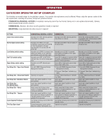
OPERATION CONTROL BOARD OVERVIEW 1 SET OPEN Button: The SET OPEN button sets the OPEN limit. See Adjust Limits section. 2 SET CLOSE Button: The SET CLOSE button sets the CLOSE limit. See Adjust Limits section. 3 MOVE GATE Buttons: The MOVE GATE buttons will either open or close the gate/door when the operator is in Limit setting mode. See Adjust Limits section. 4 BATT FAIL: • When AC power is OFF and battery voltage is critically low the gate/door will latch at a limit until AC power is restored or batteries voltage increases. • Option select switch set to OPEN forces gate/door to automatically open and then latch at the OPEN limit until AC power is restored or battery voltage increases. • Option select switch set to CLOSE forces gate/door to latch at CLOSE limit if at CLOSE limit or on next CLOSE command until AC power restored or battery voltage increases. • Constant pressure on a hard command input overrides to open or close the gate/door. • Critically low battery is less than 23 V. 5 BIPART DELAY Switch: The BIPART DELAY switch is used to select the opening speed. See page 25. 6 LEARN Button: The LEARN button is for programming remote controls and the network. 7 TIMER-TO-CLOSE dial: The TIMER-TO-CLOSE (TTC) dial can be set to automatically close the gate/door after a specified time period. The TTC is factory set to OFF. If the TTC is set to the OFF position, then the gate/door will remain open until the operator receives another command from a control. Rotate the TIMER-TO-CLOSE dial to the desired setting. The range is 0 to 180 seconds, 0 seconds is OFF. NOTE: Any radio command, single button control, or CLOSE command on the control board prior to the TTC expiring will close the gate/door. The TTC is reset by any signals from the open controls, loops, close edges, and close photoelectric sensors (IR's). 8 REVERSAL FORCE dial: The REVERSAL FORCE dial adjusts the force. See Force Adjustment section. 9 TEST BUTTONS: The TEST BUTTONS will operate the gate/door (OPEN, STOP and CLOSE). 10 STATUS LEDs: The STATUS LEDs indicate the status of the operator. See Status LED Chart in the Troubleshooting section. 11 DIAGNOSTIC CODE DISPLAY: The diagnostic code display will show the operator type, firmware version, and diagnostic codes. The operator type will display as "HC" followed by a "24" which indicates the operator type as HCTDCU. The firmware version will show after the operator type, example "1.2". 12 BACKDRIVE Switch: ALWAYS set to SECURE to enable motor braking. To manually move the gate/door see page 26. 1 2 45 6 9 7 8 3 11 10 12 24
-
 1
1 -
2
-
3
-
4
-
5
-
6
-
7
-
8
-
9
-
10
-
11
-
12
-
13
-
14
-
15
-
16
-
17
-
18
-
 19
19 -
 20
20 -
 21
21 -
 22
22 -
 23
23 -
 24
24 -
 25
25 -
 26
26 -
 27
27 -
 28
28 -
 29
29 -
30
-
31
-
32
-
33
-
34
-
35
-
36
-
37
-
38
-
39
-
40
-
41
-
42
-
43
-
44
-
45
-
46
-
47
-
48
-
49
-
50
-
51
-
52
-
53
-
54
-
55
-
56
-
57
-
58
-
59
-
60
-
61
-
62
-
63
-
64
-
65
-
66
-
67
-
68
-
69
-
70
-
71
-
72
-
73
-
74
-
75
-
76
-
77
-
78
-
79
-
80
-
81
-
82
-
83
-
84
-
85
-
86
-
87
-
88
-
89
-
90
-
91
-
92
 |
 |
