LiftMaster IPACIPDCC IPACIPDCC Door Controller Installation Manual - Page 4
Wiring
 |
View all LiftMaster IPACIPDCC manuals
Add to My Manuals
Save this manual to your list of manuals |
Page 4 highlights
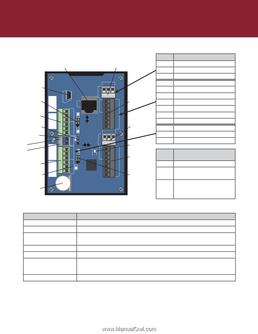
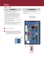
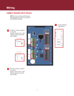
Wiring CONNECTION OVERVIEW LAN / PoE Connector ADMIN LAN DRY RLY1 WET Administrative USB Interface Door 1 Relay Power Config Jumpers NC Door 1 Relays COM NO Power Config NC Jumper COM NO External 12V Power -12IN+ + - NC COM NO Door 2 Relays NC COM NO Relay Indicator Backup Lithium Coin Battery (CR1220) PSE1 PoE DRY RLY2 WET HRTBT READER 2 RED GRN 12V BUZ GND D1 D0 IO 2 REX READER 1 IO 1 REX COM DOOR COM DOOR RED GRN 12V BUZ GND D1 D0 Door 1 I/O Door 1 Wiegand Door 2 I/O Local Heartbeat LED Door 2 Wiegand Door 2 Relay Power Config Jumpers Signal REX COM DOOR RED GREEN 12V BUZ GND D1 D0 NC COM NO Description Request-to-exit Contact Common Earth Door Contact Red LED Control Green LED Control +12VDC Power Buzzer Control Ground Wiegand Data 1 Wiegand Data 0 Normally Closed Relay Contact Common Earth Normally Opened Relay Contact Front Panel Meaning Status Solid: Unit has power Active OFF/Solid: Unit starting Blinking: Unit operational Network Orange LED: 100MBit Link Blue LED: Ntwork activity Right Bue LED: Good link Back Panel Connection Administrative USB LAN / PoE Connector Backup Lithium Battery Local Heartbeat Relay Indicator Relay Power Configuration Power Configuration Description Connect via Mini-USB to access administrative Connect to network. May also carry 802.3af/at power Battery provides power to keep time in case of primary power outage CAUTION: Disconnect before servicing. LED indicates proper function LED lights when relay is engaged (one per relay) Two jumpers select between WET and DRY modes of operation. When jumpered for WET, power is supplied through the relay in both normally closed and normally open configurations. Jumper selects between PoE and Auxiliary Power 4
-
 1
1 -
 2
2 -
 3
3 -
 4
4 -
 5
5 -
 6
6 -
 7
7 -
 8
8
 |
 |