LiftMaster IPACIPDCC IPACIPDCC Door Controller Installation Manual - Page 5
Connect Power
 |
View all LiftMaster IPACIPDCC manuals
Add to My Manuals
Save this manual to your list of manuals |
Page 5 highlights
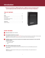
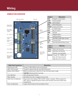
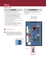
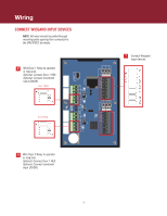
Wiring CONNECT POWER • DO NOT use ANY power supply other than those supplied with your access control panel. • DO NOT power electronic strikes and latches with the same power supply used to power the access control panel; doing so will cause DAMAGE to the access control panel. Use ONLY a UL listed access control system to power electronic strikes and latches. • DO NOT connect the power supply to a switched outlet or otherwise controlled AC outlet. • DO NOT connect the power supply to the 120 Vac outlet until ALL wiring is completed. • Install the transient noise suppression device (MOV) supplied with the access control panel for AC powered devices and Diode for DC powered devices. Do not connect DC power if POE is selected and connected. Board may be damaged and is not covered under warranty. Move jumper to Power Over Ethernet (POE) setting, if appropriate. IO 1 REX COM DOOR ADMIN LAN RED GRN 12V BUZ GND D1 D0 READER 1 DRY RLY1 WET DOOR COM IO 2 REX PSE1 1 Unpack the Door Controller. NC COM NO 2 Determine mounting location. Remove screw from NC bottom of housing and remove metal mounting plate COM which is designed to install on the face of a standard NO single gang electrical junction box with two screws. -12IN+ NC COM Connect 12V power supply. NO NC COM NO PoE DRY RLY2 HRTBT READER 2 RED GRN 12V BUZ GND D1 D0 WET -12IN+ Power Configuration Jumper 5 PoE
-
 1
1 -
 2
2 -
 3
3 -
 4
4 -
 5
5 -
 6
6 -
 7
7 -
 8
8
 |
 |